A power supply control device and a packed cell

A technology for power control devices and battery packs, which is applied in secondary batteries, battery pack components, secondary battery repair/maintenance, etc. It can solve the problems of electric vehicles not being able to drive, avoid charging, improve safety, and prevent damage Effect

Active Publication Date: 2015-07-01
MITSUBISHI MOTORS CORP
View PDF2 Cites 2 Cited by
  • Summary
  • Abstract
  • Description
  • Claims
  • Application Information

AI Technical Summary

Problems solved by technology

Here, when a part of the battery cells in the assembled battery fails, the electric vehicle may not be able to run because the current flow path of the entire assembled battery is interrupted.

Method used


Image

  • A power supply control device and a packed cell
  • A power supply control device and a packed cell
  • A power supply control device and a packed cell

Examples


no. 2 Embodiment approach

[0150] Next, a second embodiment of the present invention will be described with reference to the drawings.

[0151] The assembled battery according to the present embodiment is mounted on an electric vehicle running by driving a motor using electric power, and is used as a running battery for storing electric power for running the electric vehicle.

[0152] First, the electrical configuration of a general battery pack will be described.

[0153] Such as Figure 8 As shown, the assembled battery 20010 includes a plurality of battery cells 20012 connected in series; and a plurality of rectifying elements 20018 connected in parallel to each of the plurality of battery cells 20012 to supply power to the load R (motor).

[0154] Among the plurality of battery cells 20012, when any battery cell 20012 fails, the current flows through the rectifying element 20018 connected to the battery cell 20012, so that the power supply from the assembled battery 20010 to the load R can be maint...

no. 3 Embodiment approach

[0208] Next, refer to Figure 11 The third embodiment will be described.

[0209] In addition, in the following embodiment, the same code|symbol is attached|subjected to the same part and member as 2nd Embodiment, and description is abbreviate|omitted.

[0210] In the third embodiment, the wiring structure of the rectifying element 20018, the positive terminal 20022A, and the negative terminal 20022B is different from that of the second embodiment, and other points are the same as those of the second embodiment.

[0211] Such as Figure 11 As shown, the rectifier element 20018 has an anode terminal 21804 and a cathode terminal 21806 provided on a main body 21802. The main body 21802 has a heat dissipation plate 21802B for dissipating heat from the main body 21802. The anode terminal 21804 is connected to the negative terminal via the second wiring 20028 (wiring). 20022B is electrically connected, which is the same as the second embodiment.

[0212] In the third embodiment, ...


PUM


Abstract

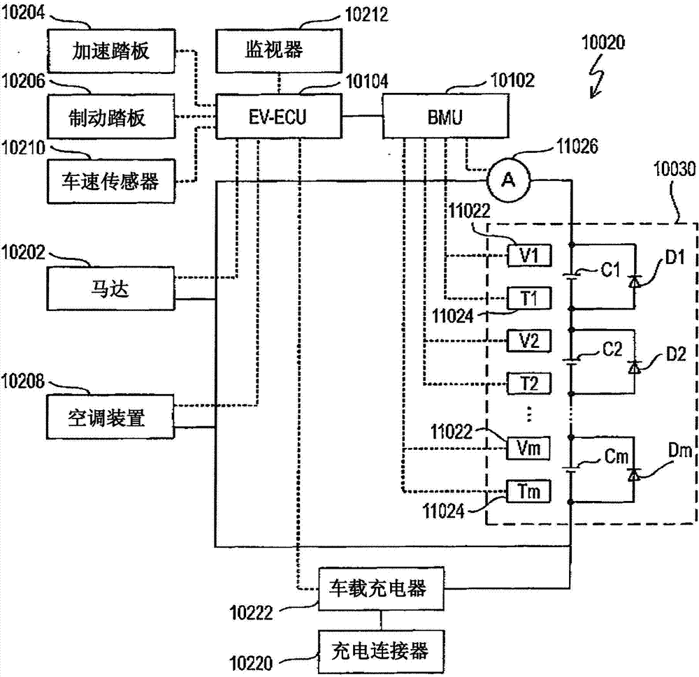
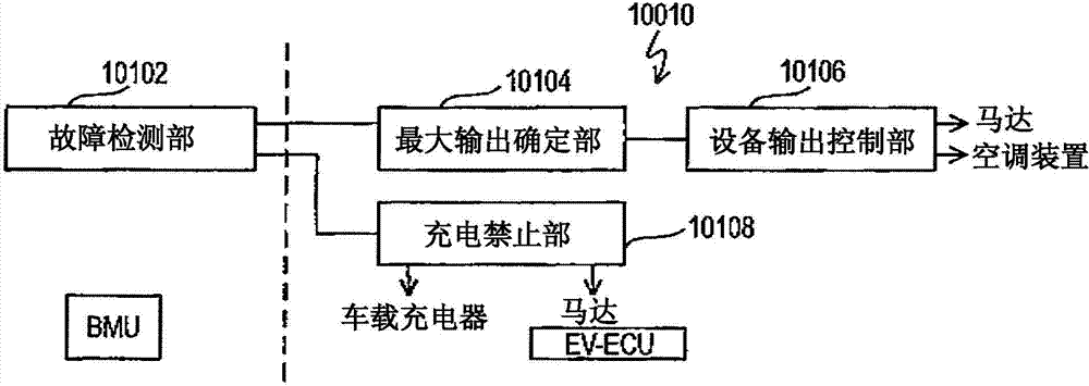
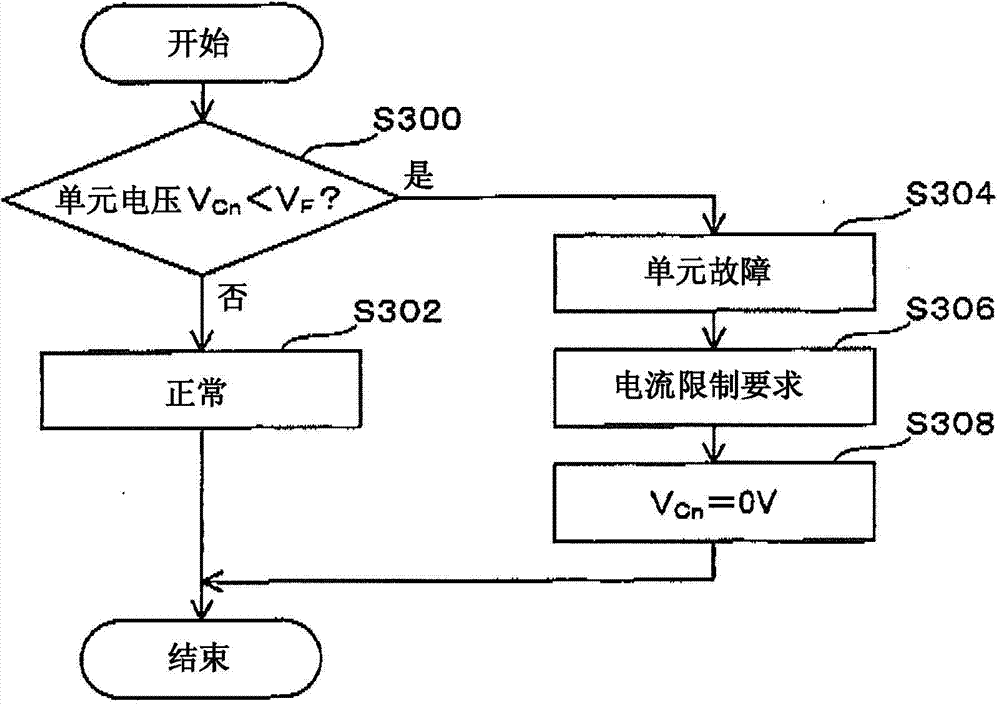
A power supply control device and a packed cell are provided. Load to the packed cell is properly controlled when cell units break down. The packed cell (10030) comprises a plurality of cell units (Cn) in series connection; and a plurality of rectifying elements (Dn) that are connected in parallel to the cell units (Cn). When breakdown of any cell unit (Cn) is detected, the maximum output power of the packed cell (10030) is determined based on the maximum allowable current of the rectifying elements (Dn), and output of devices receiving electric supply from the packed cell (10030) and running is controlled. The maximum output power is determined as the product of the maximum allowable current of the rectifying elements (Dn) and output voltage of the packed cell (10030) except the breakdown cell unit (Cn).

Description

technical field [0001] The present invention relates to a power source control device for controlling an assembled battery including a plurality of battery cells connected in series. [0002] In addition, the present invention relates to a battery pack including a plurality of battery cells connected in series. Background technique [0003] Conventionally, an electric vehicle running on electric power has mounted a battery pack configured to obtain a high voltage by connecting a plurality of battery cells in series. Here, when a part of the battery cells in the assembled battery fails, the electric vehicle may not be able to run because the current flow path of the entire assembled battery is disconnected. In order to avoid this phenomenon, it is possible to connect rectification elements (diodes, more specifically, Schottky barrier diodes, etc.) A limited movement action (limp-home) is performed (see, for example, Patent Document 1 below). [0004] prior art literature ...

Claims


Application Information

Patent Timeline
Patent Type & Authority Applications(China)
IPC IPC(8): H01M2/02H01M2/30H01M10/613H01M50/102H01M50/569
CPCH01M10/42Y02E60/10
Inventor 铃木浩恭斋藤润
Owner MITSUBISHI MOTORS CORP
Why Eureka
Try Eureka