Thermal protection circuit

A thermal protection and circuit technology, used in emergency protection circuit devices, circuit devices, and automatic disconnection emergency protection devices, etc., can solve problems such as circuit device burnout and FET source and drain breakdown.

Inactive Publication Date: 2015-07-01
WARECONN TECH SERVICE (TIANJIN) CO LTD +1
View PDF0 Cites 5 Cited by
  • Summary
  • Abstract
  • Description
  • Claims
  • Application Information

AI Technical Summary

Problems solved by technology

[0002] The field effect tube is a heating element. If it is overheated during use, the source and drain of the field effect tube may be broken down. After the breakdown, it is easy to cause the devices in the circuit to be burned

Method used


Image

  • Thermal protection circuit

Examples


Embodiment Construction

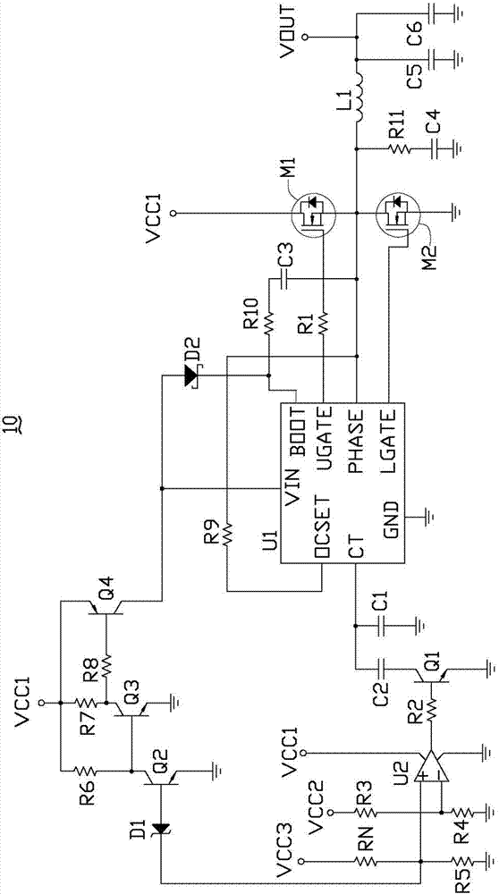
[0013] Please refer to figure 1 A preferred embodiment of the thermal protection circuit 10 of the present invention includes a control chip U1, an operational amplifier U2, resistors R1-R11, capacitors C1-C6, transistors Q1-Q4, field effect transistors M1 and M2, diodes D1 and D2, and inductors L1.

[0014] The frequency adjustment pin CT of the control chip U1 is grounded through the capacitor C1, the frequency adjustment pin CT of the control chip U1 is also connected to the collector of the transistor Q1 through the capacitor C2, and the first drive pin of the control chip U1 UGATE is connected to the gate of the field effect transistor M1 through the resistor R1, the source of the field effect transistor M1 is connected to the drain of the field effect transistor M2, and the drain of the field effect transistor M1 is connected to the first voltage terminal VCC1, so The source of the field effect transistor M2 is grounded, the gate of the field effect transistor M2 is con...


PUM


Abstract

A thermal protection circuit comprises a control chip, an operational amplifier, a thermistor, a plurality of triodes and a plurality of capacitive resistors. Resistance of the thermistor changes along with changes of temperature, when the temperature does not exceed first preset temperature, the control chip operates normally; when the temperature exceeds the first preset temperature and does not exceed second preset temperature, working frequency of the control chip drops and the temperature drops; and when the temperature exceeds the second preset temperature, the control chip is power-off and stops working. Due to the thermal protection circuit, a circuit element can be effectively prevented from being overheated and burnt down.

Description

technical field [0001] The invention relates to a thermal protection circuit. Background technique [0002] The field effect tube is a heating element. If it is overheated during use, the source and drain of the field effect tube may be broken down. After the breakdown, it is easy to cause the devices in the circuit to be burned. Contents of the invention [0003] In view of this, it is necessary to provide a thermal protection circuit to prevent the field effect tube from being burned due to overheating. [0004] A thermal protection circuit comprising: [0005] A control chip, the frequency adjustment pin of the control chip is grounded through the first capacitor, the frequency adjustment pin of the control chip is also connected to the first end of the first electronic switch through the second capacitor, the first terminal of the control chip A driving pin is connected to the gate of the first field effect transistor through a first resistor, the source of the first...

Claims


Application Information

Patent Timeline
Patent Type & Authority Applications(China)
IPC IPC(8): H02H7/20H02H5/04
Inventor 周海清
Owner WARECONN TECH SERVICE (TIANJIN) CO LTD
Why Eureka
Try Eureka