Fan motor brake device and control method thereof

A fan motor and brake device technology, which is applied in the direction of electric motor/converter plugs, AC motor deceleration devices, etc., can solve the problems of fan motors that cannot be started smoothly, burnt out, and unstable

Active Publication Date: 2015-07-01
DELTA ELECTRONICS INC
View PDF6 Cites 8 Cited by
  • Summary
  • Abstract
  • Description
  • Claims
  • Application Information

AI Technical Summary

Problems solved by technology

However, due to the different settings and usage conditions of the servo machines in the server room, the fan motors that are not running are easily affected by the return air generated by the surrounding fan motor

Method used


Image

  • Fan motor brake device and control method thereof
  • Fan motor brake device and control method thereof
  • Fan motor brake device and control method thereof

Examples


Embodiment Construction

[0053] Hereby, the technical content and detailed description of the present invention are described as follows in conjunction with the drawings:

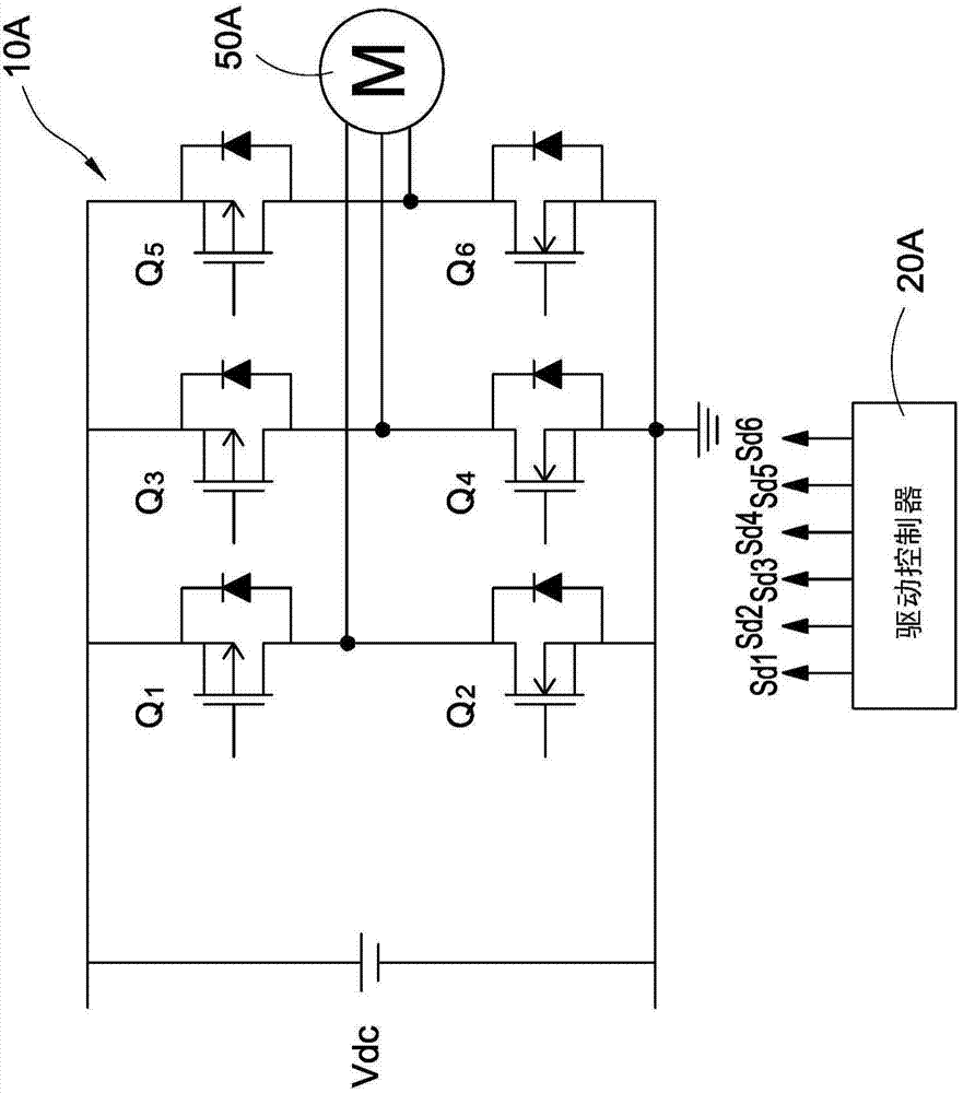
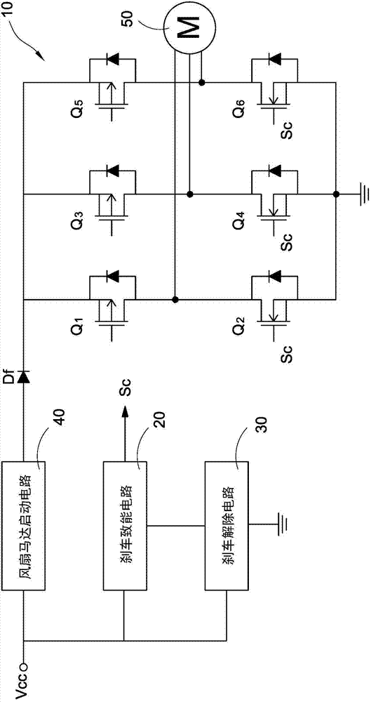
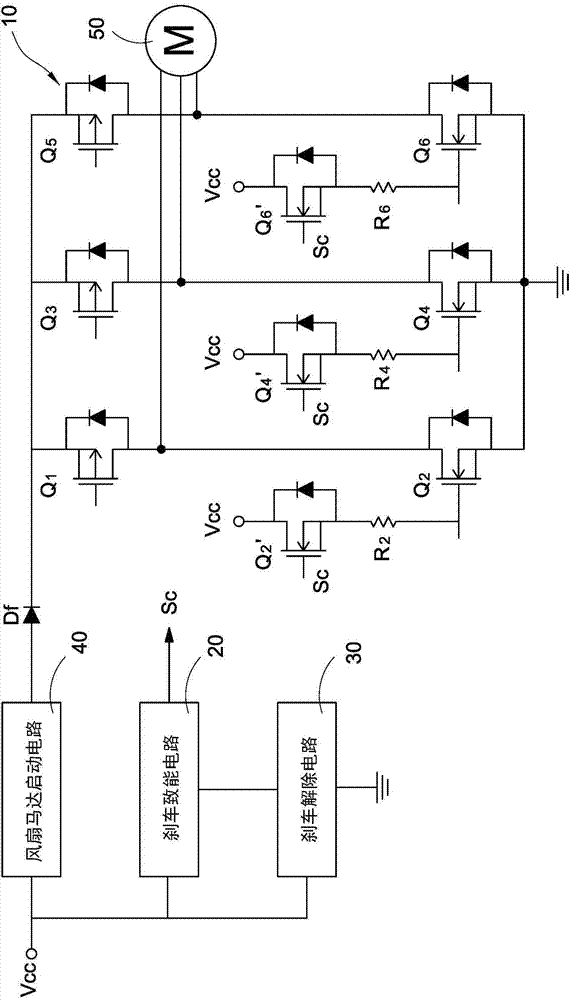
[0054] See Figure 2A It is a schematic diagram of a circuit module in a preferred embodiment of the fan motor braking device of the present invention. The fan motor braking device provides braking protection before the fan motor 50 starts. The fan motor brake device includes a conversion circuit 10 , a brake enable circuit 20 , a brake release circuit 30 and a fan motor start circuit 40 . The conversion circuit 10 has a plurality of power switching elements and is electrically connected to the fan motor 50 .

[0055] Such as Figure 2A As shown, in this preferred embodiment, the fan motor 50 is a three-phase DC motor (three-phase DC motor), therefore, the corresponding conversion circuit 10 is three groups of bridge arm structures connected in parallel, and each A group of bridge arms is connected in series by two power switch...


PUM


Abstract

The invention discloses a fan motor brake device for providing brake protection before a fan motor starts, which comprises a conversion circuit, a brake enabling circuit, a brake release circuit and a fan motor start circuit, wherein the conversion circuit is provided with multiple power switch elements and electrically connected with the fan motor; the brake enabling circuit is connected with the conversion circuit; the brake release circuit is connected with the brake enabling circuit; and the fan motor start circuit receives an outer DC voltage. When the brake enabling circuit receives the outer DC voltage, the brake enabling circuit generates a brake control signal to conduct the power switch elements so as to brake the fan motor.

Description

technical field [0001] The invention relates to a fan motor brake device and its control method, in particular to a fan motor brake device with a brake protection function before starting the fan motor and its control method. Background technique [0002] See figure 1 , figure 1 It is a schematic diagram of a circuit driven by a fan motor in the prior art. As shown in the figure, the fan motor drive circuit structure includes a conversion circuit 10A, a drive controller 20A and a fan motor 50A. The conversion circuit 10A has a plurality of power switching elements Q1 - Q6 and is electrically connected to the fan motor 50A. Taking the fan motor 50A as a three-phase DC motor as an example, the conversion circuit 10A has three sets of bridge arms connected in parallel, and each set of bridge arms is connected in series by two power switching elements. The conversion circuit 10A receives an external DC voltage Vdc and converts it into the power required by the fan motor 50A....

Claims


Application Information

Patent Timeline
IPC IPC(8): H02P3/24
Inventor 曾伟硕吴家丰刘铭龙梁佑任
Owner DELTA ELECTRONICS INC
Why Eureka
Try Eureka