
LED constant current driver

A constant current driver and constant current control technology, applied in lighting devices, light sources, electric light sources, etc., can solve the problems of increased loss of regulating tubes and control units, reduced efficiency of constant current drivers, etc., and achieve the effect of low ripple

Active Publication Date: 2015-07-01
OPPLE LIGHTING
View PDF6 Cites 2 Cited by
  • Summary
  • Abstract
  • Description
  • Claims
  • Application Information

AI Technical Summary

Problems solved by technology

However, when the LED load voltage of this constant current driver changes, the loss of the adjustment tube and the control unit will increase, which will reduce the efficiency of the constant current driver.

Method used


Image

  • LED constant current driver
  • LED constant current driver
  • LED constant current driver

Examples


Embodiment Construction

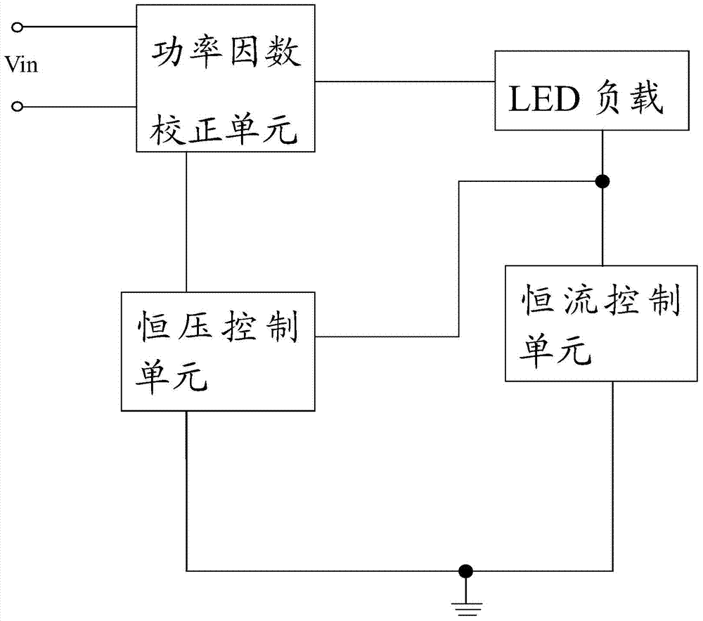
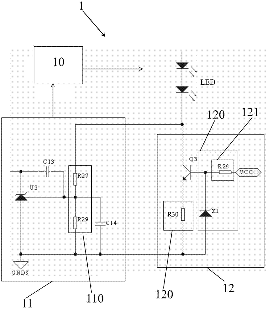
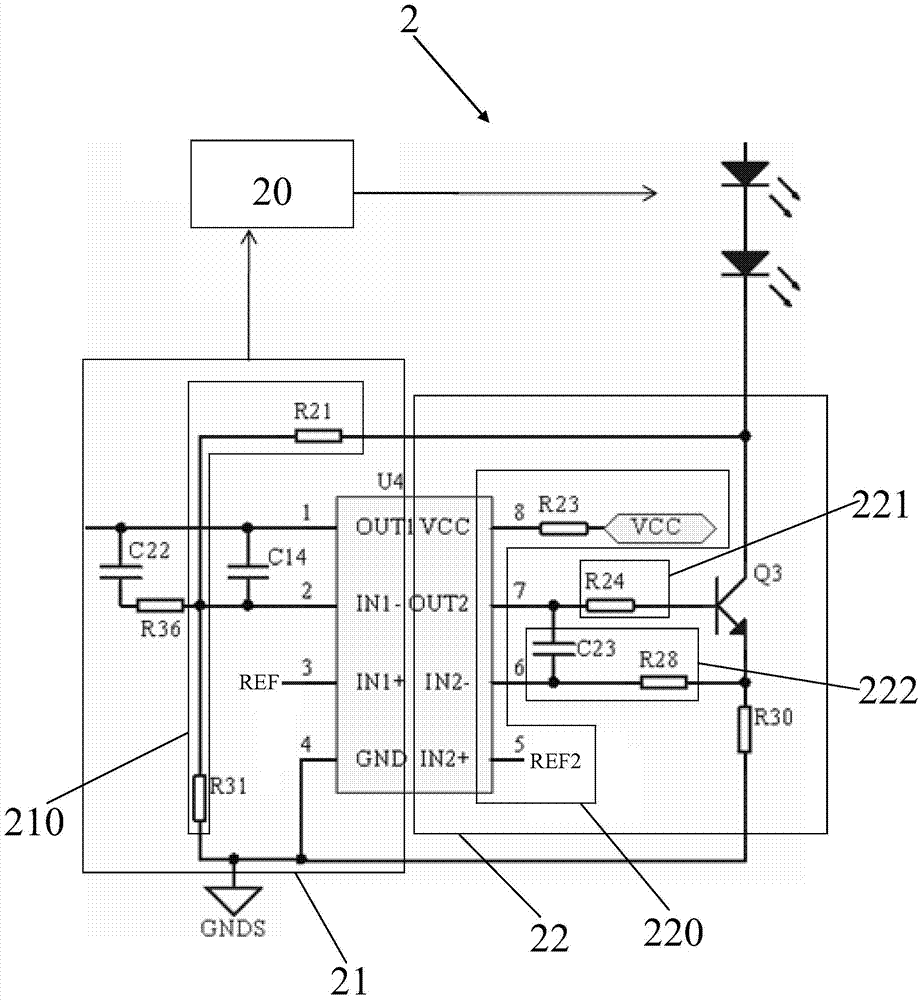
[0018] Please refer to figure 1 As shown, an LED constant current driver of the present invention provides constant current drive for LED loads, and includes a power factor correction unit, a constant voltage control unit and a constant current control unit. The first end of the constant current control unit is connected to the negative end of the LED load, and one end of the constant voltage control unit is connected between the constant current control unit and the negative end of the LED load. The constant current control unit controls the current flowing through the LED load, and the constant voltage control The unit controls the voltage of the first terminal of the constant current control unit. The LED constant current driver of the present invention uses a power factor correction unit to provide voltage for the LED load. On the one hand, it provides a constant current control unit connected to the negative terminal of the LED load to control the constant current flowing...


PUM


Abstract

Disclosed is an LED constant-current driver, which provides constant-current drive for an LED load and comprises a power factor correction unit, a constant-voltage control unit and a constant-current control unit, wherein a first end of the constant-current control unit is connected to a load end of the LED load, and one end of the constant-voltage control unit is connected between the constant-current control unit and the load end of the LED load. The constant-current control unit controls a current which flows through the LED load, and the constant-voltage control unit controls a voltage at the first end of the constant-current control unit.

Description

【Technical field】 [0001] The invention relates to a constant current driver, in particular to a constant current drive circuit of an illuminating device. 【Background technique】 [0002] LED has the characteristics of long life, high luminous efficiency and low power. In the LED driving power supply, a unipolar power factor adjustment (PFC) circuit is often used to drive the LED. Such a circuit is simple and low in cost. Existing unipolar PFC circuits usually adopt two methods. The first is to directly output a constant current. This way the output current has a large ripple and requires a large-capacity electrolytic capacitor for filtering, which leads to an increase in the size and cost of the circuit. The second type, as disclosed in Chinese Patent Application Publication No. CN102843808A, discloses a constant current driver for light emitting diodes, which includes a single-stage PFC circuit, a regulator tube, and a control unit. The input end of the single-stage PFC c...

Claims


Application Information

Patent Timeline
IPC IPC(8): H05B37/02
CPCH05B37/02H05B45/395Y02B20/30
Inventor 余世伟朱元
Owner OPPLE LIGHTING
Learn More