Film-forming apparatus

A technology of film forming device and mounting part, which is applied to spray devices, spray devices, liquid spray devices, etc., can solve the problems of large-scale, difficult maintenance, and heavy-duty water mist supply parts, shortening the conveying distance, and inhibiting condensation. Effect

Active Publication Date: 2015-07-01
TOSHIBA MITSUBISHI-ELECTRIC IND SYST CORP
View PDF7 Cites 3 Cited by
  • Summary
  • Abstract
  • Description
  • Claims
  • Application Information

AI Technical Summary

Problems solved by technology

Therefore, in the film forming apparatus to which the "spray method" is applied,

Method used


Image

  • Film-forming apparatus
  • Film-forming apparatus
  • Film-forming apparatus

Examples


Embodiment approach

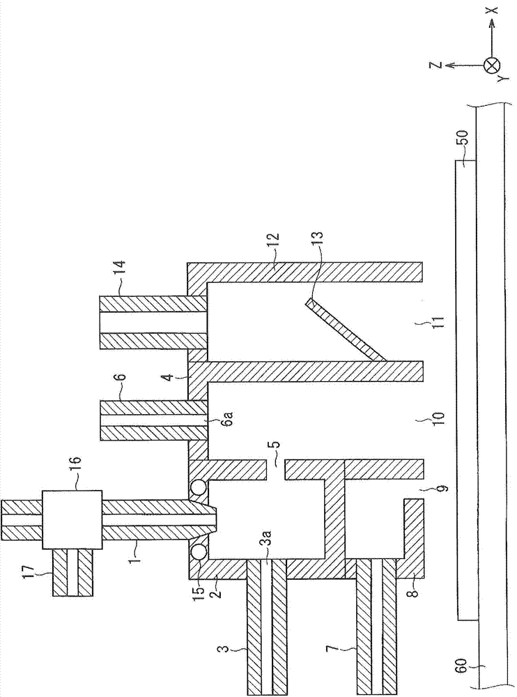
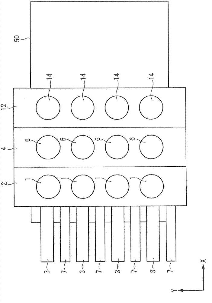
[0033] figure 1 It is a cross-sectional view showing the structure of a main part (more specifically, the vicinity of a solution spraying part that sprays a solution onto a substrate in a mist form) of the film forming apparatus according to this embodiment. here, figure 1 The X-Y-Z directions are shown in . in addition, figure 2 is shown from figure 1 Observation from above figure 1 A top view of the composition of the structure shown. here, figure 2 The X-Y direction is shown. In addition, in figure 2 In order to simplify the drawings, the illustration of the constituent members 16, 17, 60 is omitted.

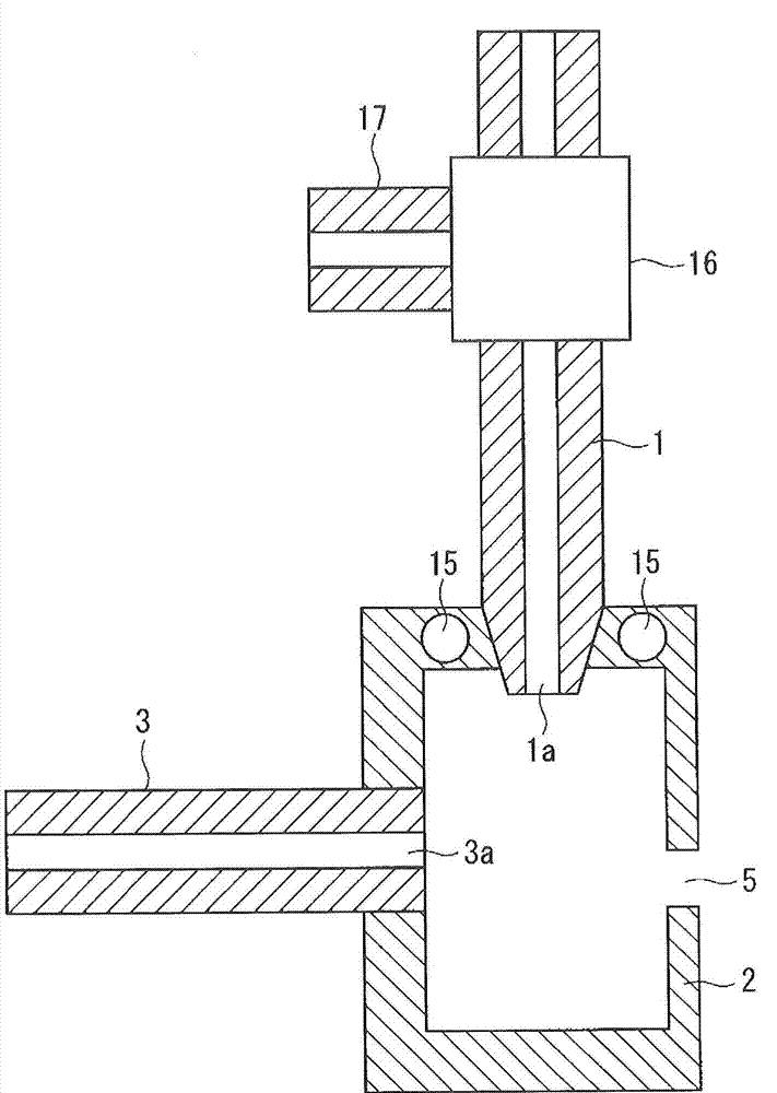
[0034] in addition, image 3 is showing figure 1 Shown is an enlarged cross-sectional view of the structure of the first chamber 2 and the components 1 , 3 etc. connected to the first chamber 2 . in addition, Figure 4 is showing figure 1 Shown is an enlarged cross-sectional view of the structure of the second chamber 4 and of the component parts 6 connected t...


PUM


Abstract

The present invention provides a film-forming apparatus, which is capable of forming, on a substrate, a film having excellent film qualities, and which is capable of effectively using a solution in a film-forming process, said film-forming apparatus having a small size as a whole. This film-forming apparatus is provided with a spray nozzle (1), a first chamber (2), a first gas supply port (3a), a second chamber (4), a through hole (5), and a spraying port (10). The solution jetted in a droplet form from the spray nozzle (1) is stored in the first chamber (2), and the solution is atomized in the first chamber (2) by means of a gas supplied through the first gas supply port (3a). The atomized solution moves from the first chamber (2) to the second chamber (4) through the through hole (5), and is sprayed toward a substrate (50) from the spraying port (10) that is provided in the second chamber (4).

Description

technical field [0001] The present invention relates to a film forming apparatus for forming a film on a substrate. Background technique [0002] Conventionally, there are "jet method" and "spray method" as methods for forming a film on a substrate. Here, in the "jet method", liquid droplets of about 10 μm to 100 μm are jetted toward the substrate. On the other hand, in the "spray method", a water mist of about several μm is sprayed on the substrate in mist form. [0003] In addition, in the "jet method", generally, a two-fluid nozzle is used which collides a gas with a solution to form droplets of the solution to a size of about several tens of μm. On the other hand, in the "spray method", the solution is atomized into a fine mist of several μm by an ultrasonic vibrator, etc., and the atomized solution is transported to the reaction chamber (or spray port) where the substrate is placed through a long pipe. . [0004] In addition, there is Patent Document 1 as a prior do...

Claims


Application Information

Patent Timeline
IPC IPC(8): B05B7/04B05B7/08B05B13/00
CPCB05B15/0406B05B7/0483B05B15/0431C23C16/4486B05B7/0012B05B1/044B05B15/025B05B14/00B05B15/55B05B12/18B05B7/0075B05B7/0861B05B7/0807C23C16/4412C23C16/455C23C16/46
Inventor 白幡孝洋织田容征平松孝浩
Owner TOSHIBA MITSUBISHI-ELECTRIC IND SYST CORP
Why Eureka
Try Eureka