


Quick Research
Generate reliable direction feasibility study reports for your R&D in just a few steps.

Technical Q&A
Discover and master advanced knowledge NOW. Basics, ideas, possibilities, all at once.

Find Solutions
As an expert in R&D theories, this can generate solutions to your technical problems instantly.

Evaluate Feasibility
Analyze your overall solution with one click, know your potential R&D risks in advance.

Monitor Landscape
Get weekly tech updates, stay abreast of the latest tech innovations and key insights.
Fuel injection arrangement
A technology of fuel injection device and fuel injection valve, which is applied in the direction of fuel injection device, special fuel injection device, charging system, etc., can solve problems such as increasing the complexity of the engine
- Summary
- Abstract
- Description
- Claims
- Application Information
AI Technical Summary
Problems solved by technology
Method used
Image

Examples
Embodiment Construction
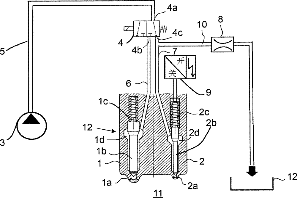
[0011] The fuel injection device according to the invention is particularly suitable for large internal combustion engines, such as main or auxiliary engines of ships, engines for offshore applications or engines used at power plants for generating electricity. The invention is particularly advantageous in dual fuel engines which can operate on both liquid and gaseous fuels and where a small amount of liquid pilot fuel is used when the engine is operated in gaseous mode. However, the invention may also be used in other engines in which two or more fuel injectors are used per cylinder.
[0012] figure 1 A schematic diagram of a fuel injection device according to an embodiment of the present invention is shown. The fuel injection device comprises a first fuel injection valve 1 and a second fuel injection valve 2 which are arranged for injecting fuel into a cylinder 11 of a piston engine. The second fuel injection valve 2 is configured to inject a smaller amount of fuel than th...
PUM
 Abstract
Description
Claims
Application Information
 - R&D Engineer
- R&D Manager
- IP Professional
- Industry Leading Data Capabilities
- Powerful AI technology
- Patent DNA Extraction
Browse by: Latest US Patents, China's latest patents, Technical Efficacy Thesaurus, Application Domain, Technology Topic, Popular Technical Reports.
© 2024 PatSnap. All rights reserved.Legal|Privacy policy|Modern Slavery Act Transparency Statement|Sitemap|About US| Contact US: help@patsnap.com