Digestive endoscopy conveying mechanism

A conveying mechanism and endoscope technology, applied in the field of medical devices, can solve the problems of high physical exertion, expensive operation facilities, high pollution, etc., and achieve the effects of preventing mutual pollution, accurate and reliable movement, and protecting the outer wall.

Active Publication Date: 2015-07-08
SHENYANG INST OF AUTOMATION - CHINESE ACAD OF SCI
View PDF8 Cites 8 Cited by
  • Summary
  • Abstract
  • Description
  • Claims
  • Application Information

AI Technical Summary

Problems solved by technology

[0002] Digestive endoscopy has become a routine method for the diagnosis and treatment of gastrointestinal diseases, but the operating facilities of conventional digestive endoscopy are expensive, and digestive endoscopy is often accompanied by high pollution risks, which makes medical staff perform digestive endoscopy. During speculum examination, the physical exertion is huge and the infection and radiation are extremely vulnerable

Method used


Image

  • Digestive endoscopy conveying mechanism
  • Digestive endoscopy conveying mechanism
  • Digestive endoscopy conveying mechanism

Examples


Embodiment 1

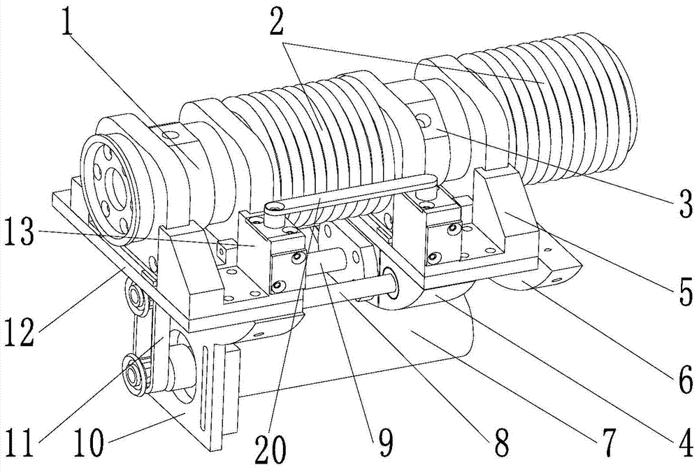
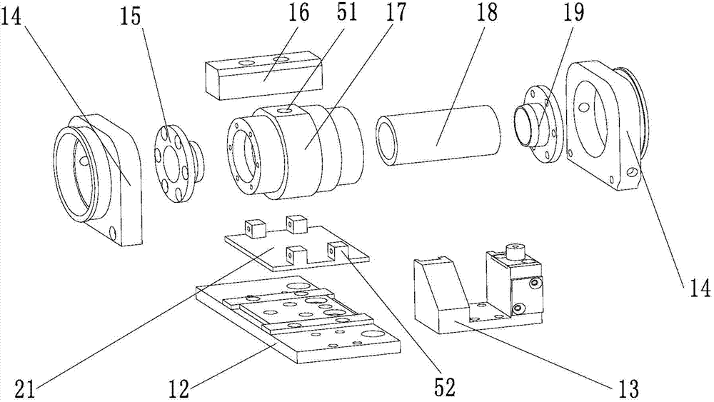
[0033] Such as figure 2 As shown, in this embodiment, both the fixed air clamp 1 and the dynamic air clamp 3 are integral structures, including an air clamp cylinder 17, a first gland 15, a second gland 19, a silicone tube 18 as a silicone clamping body, Air clamp end fixing seat 14, air clamp base 16, air clamp bottom plate 21 and air clamp locking mechanism 13, described air clamp cylinder body 17 is tubular structure, silicone tube 18 is arranged in the described air clamp cylinder body 17, described The first gland 15 and the second gland 19 are respectively installed on the two ends of the air clamp cylinder 17 along the axial direction, and the air clamp cylinder 17, the first gland 15, the second gland 19 and the silicone tube 18 constitutes an airtight air chamber arranged between the inner peripheral surface of the air clamp cylinder 17 and the outer peripheral surface of the silicone tube 18, the air clamp cylinder 17 is provided with air holes 51, during work, thro...

Embodiment 2

[0040] Such as Figure 5-6 As shown, in this embodiment, both the fixed air clamp 1 and the dynamic air clamp 3 are split structures, including an air clamp base 41, an air clamp upper cover 36, an air clamp clamping piece 39, a hinge 37, a self-locking buckle 40 and as The two silica gel half-membranes 38 of the silica gel clamping body, the air clamp base 41 are installed on the platen base 30 of the spring platen mechanism 12, and one side of the air clamp loam cake 36 is hinged with the air clamp base 41 by a hinge 37. The hinge 37 is a butterfly hinge, and the other side of the air clamp upper cover 36 is connected and locked with the air clamp base 41 through a self-locking buckle 40; There are grooves with the same depth, and the silicone half-membranes 38 are respectively arranged in the grooves of the air clamp base 41 and the air clamp upper cover 36, and are respectively fixed on the air clamp upper cover 36 and the air clamp by the air clamp clamping piece 39. On ...

Embodiment 3

[0045] Such as Figure 7-8As shown, in this embodiment, both the fixed gas clamp 1 and the dynamic gas clamp 3 are split structures. The fixed gas clamp 1 of this embodiment is the same as that of embodiment 2. The difference between this embodiment and embodiment 2 is that There is a load cell 45, and the specific structure is: including a fixed base 47, a load cell 45, a fixed nut 46, a force feedback air clamp base 43, an air clamp upper cover 36, an air clamp clamping piece 39, and two silicone half-membranes 38 , hinge 37 and spring self-locking buckle 44, wherein the fixed base 47 is installed on the platen base 30 of the spring platen mechanism 12 through screws, and a pair of opposite corners of the fixed base 47 are provided with two sensor brackets 58, force feedback The air clamp base 43 is provided with two sensor support plates 59, and two load cells 45 are arranged in parallel between the fixed base 47 and the force feedback air clamp base 43, and one end of each...


PUM


Abstract

The invention relates to the field of medical instruments, in particular to a digestive endoscopy conveying mechanism. The digestive endoscopy conveying mechanism comprises a fixed air clamp, a movable air clamp, a nut bed, a driving motor, a motor fixing plate, a limiting plate, a transmission mechanism and a spring bearer plate mechanism, wherein a linear guide rod and a lead screw are arranged between the motor fixing plate and the limiting plate; the lead screw is connected with the driving motor through the transmission mechanism; the nut bed sleeves the lead screw and the linear guide rod; the fixed air clamp and the movable air clamp are respectively mounted on the motor fixing plate and the nut bed through the spring bearer plate mechanism and are alternately inflated; the movable air clamp is driven to convey by the driving motor when inflated for clamping a digestive endoscopy, and the fixed air clamp is driven to return by the reversed driving motor when inflated for clamping the digestive endoscopy; the fixed air clamp and the movable air clamp adopt an integrated or separated structure; and a force transducer can be further arranged on the movable air clamp. The digestive endoscopy conveying mechanism adopts the pneumatic clamping mode to replace a hand for conveying the digestive endoscopy, is simple in structure and can prevent infection and radiation.

Description

technical field [0001] The invention relates to the field of medical instruments, in particular to a digestive endoscope delivery mechanism. Background technique [0002] Digestive endoscopy has become a routine method for the diagnosis and treatment of gastrointestinal diseases, but the operating facilities of conventional digestive endoscopy are expensive, and digestive endoscopy is often accompanied by high pollution risks, which makes medical staff perform digestive endoscopy. During speculum examination, the physical exertion is huge and the patient is extremely vulnerable to infection and radiation. Contents of the invention [0003] The purpose of the present invention is to provide a digestive endoscope delivery mechanism, which simulates the manual delivery of the digestive endoscope by means of pneumatic clamping, has a simple structure and can effectively prevent medical staff from being infected and irradiated. [0004] The purpose of the present invention is ...

Claims


Application Information

Patent Timeline
Patent Type & Authority Applications(China)
IPC IPC(8): A61B1/00
Inventor 李贵祥杨臻达刘浩杨云生李洪谊
Owner SHENYANG INST OF AUTOMATION - CHINESE ACAD OF SCI
Why Eureka
Try Eureka