Self-driven bogie structure rail vehicle
A rail vehicle and bogie technology, which is applied in the field of self-propelled bogie structure rail transport vehicles, can solve the problems that unpowered rail vehicles cannot meet actual operation needs, achieve considerable economic and social benefits, and solve process layout problems , the effect of improving equipment utilization
- Summary
- Abstract
- Description
- Claims
- Application Information
AI Technical Summary
Problems solved by technology
Method used
Image
Examples
Embodiment 1
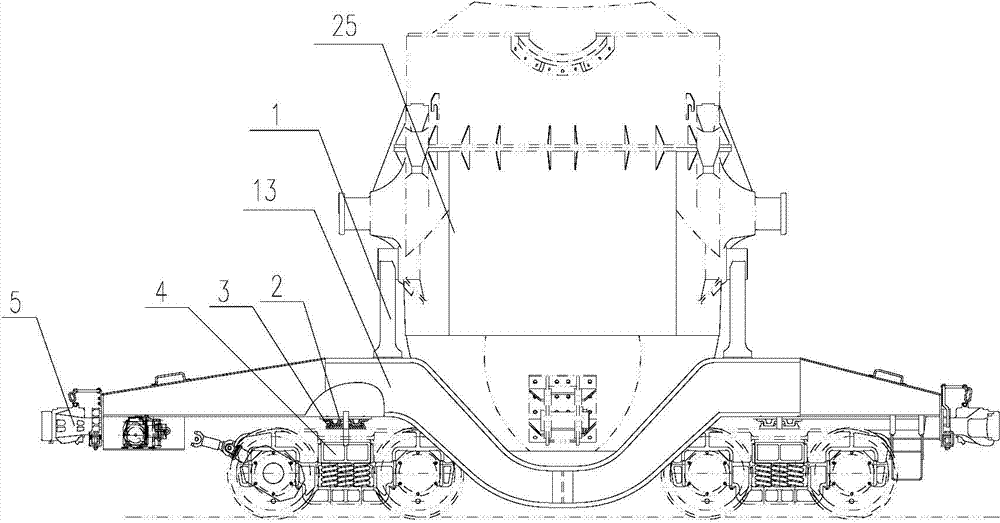
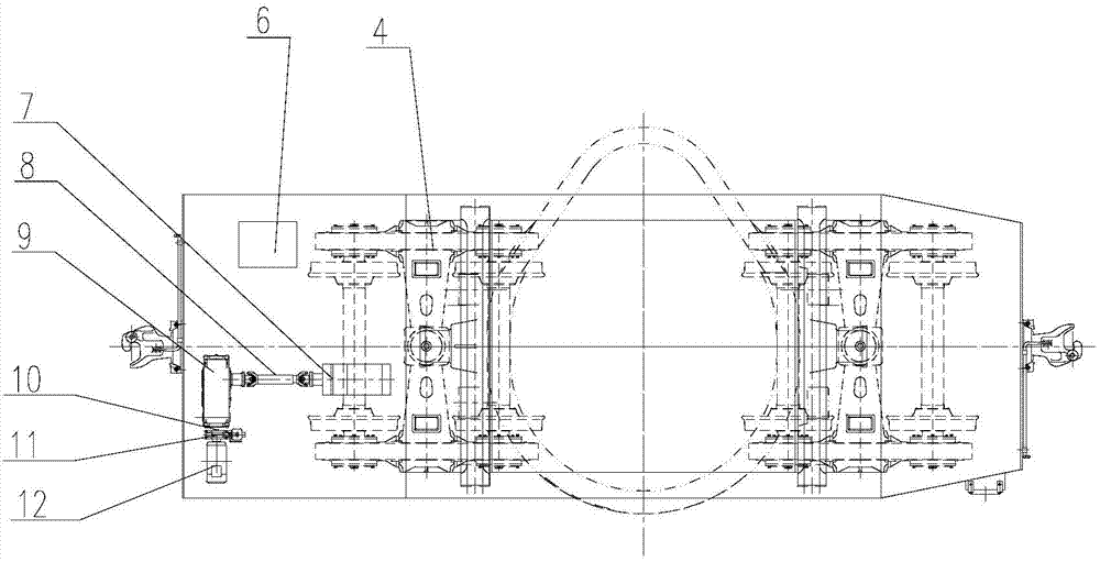
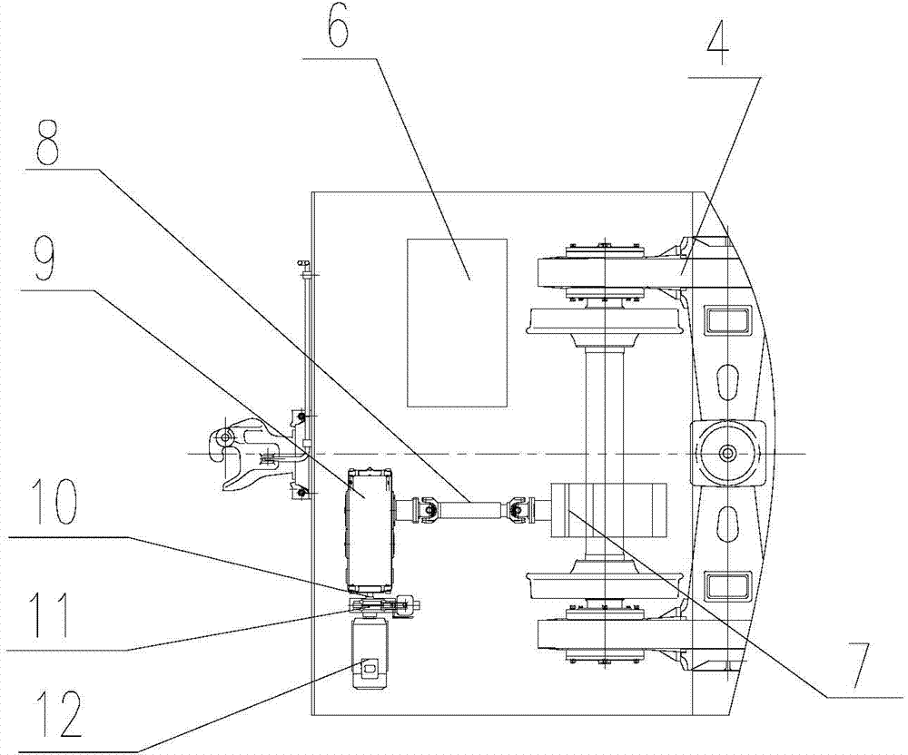
[0033] Such as Figure 1-Figure 6 As shown, the rail vehicle with a self-propelled bogie structure in Embodiment 1 includes two bogies 4 and a vehicle frame 13 installed above the two bogies 4 and connected in rotation with the two bogies 4 respectively. Such as figure 1 As shown, the two ends of the vehicle frame 13 are also provided with coupler buffer devices 5 respectively, which can realize two vehicles being connected or pulled by a locomotive when a failure occurs. Such as figure 1 , figure 2 and image 3 As shown, in this embodiment, each bogie 4 includes at least two axles 22, wherein one axle 22 is provided with a commutator 7 that drives it to rotate, and the axle 22 on which the commutator 7 is installed is a drive shaft. 221. One end of the vehicle frame 13 is provided with a drive system for driving the commutator 7, and a brake is also provided on one of the axles 22 or the drive system. The function of the drive system is to provide power for the entire ...
Embodiment 2
[0044] The difference between the second embodiment and the first embodiment lies in the difference of the driving system. Such as Figure 8 and Figure 9 As shown, the drive system of the self-propelled bogie structure rail vehicle of Embodiment 2 includes a diesel engine 171, and the transmission mechanism includes a second universal transmission mechanism 81, a hydraulic torque converter 92 and a third universal transmission mechanism 82; The diesel engine 171 is connected to the hydraulic torque converter 92 through the second universal transmission mechanism 81 , and the hydraulic torque converter 92 is connected to the commutator 7 through the third universal transmission mechanism 82 . Both the second universal transmission mechanism 81 and the third universal transmission mechanism 82 include a transmission shaft and universal joints arranged at both ends of the transmission shaft. The brake is arranged on the commutator 7, and a friction plate is arranged on its out...
Embodiment 3
[0046] The difference between the third embodiment and the first embodiment lies in the difference of the driving system. Such as Figure 10 and 11 As shown, the drive system of the self-propelled bogie structure rail vehicle of embodiment three includes a diesel engine 171, a hydraulic pump 94, a hydraulic control valve group 51 and a hydraulic motor 85, and the hydraulic motor 85 is directly connected with the commutator 7; the diesel engine 171 drives the hydraulic pump 94 to rotate to compress the hydraulic medium. The flow direction and on-off of the hydraulic medium are controlled by the hydraulic control valve group 51. The hydraulic control valve group 51 is connected to the hydraulic motor 85 through the hydraulic hose 52 to drive the hydraulic motor 85 to rotate. The hydraulic motor 85 drives the commutator 7, so that the axle 22 rotates together with the wheels 21 to realize smooth running.
[0047] The hydraulic station 61 and the hydraulic control valve group 51...
PUM
 Abstract
Description
Claims
Application Information
 - R&D
- Intellectual Property
- Life Sciences
- Materials
- Tech Scout
- Unparalleled Data Quality
- Higher Quality Content
- 60% Fewer Hallucinations
Browse by: Latest US Patents, China's latest patents, Technical Efficacy Thesaurus, Application Domain, Technology Topic, Popular Technical Reports.
© 2025 PatSnap. All rights reserved.Legal|Privacy policy|Modern Slavery Act Transparency Statement|Sitemap|About US| Contact US: help@patsnap.com


