Self-propelled bogie structure rail vehicle

A rail vehicle and bogie technology, which is applied in the field of self-propelled bogie structure rail transport vehicles, can solve the problem that unpowered rail vehicles cannot meet actual operation needs, achieve considerable economic and social benefits, reduce equipment cost, The effect of solving process layout problems

Active Publication Date: 2018-06-01
QINHUANGDAO QINYE HEAVY IND
View PDF11 Cites 0 Cited by
  • Summary
  • Abstract
  • Description
  • Claims
  • Application Information

AI Technical Summary

Problems solved by technology

The disadvantage of the prior art is that unpowered rail vehicles cannot meet the needs of actual operations

Method used


Image

  • Self-propelled bogie structure rail vehicle
  • Self-propelled bogie structure rail vehicle
  • Self-propelled bogie structure rail vehicle

Examples


Embodiment 1

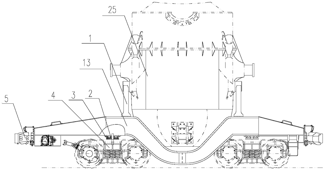
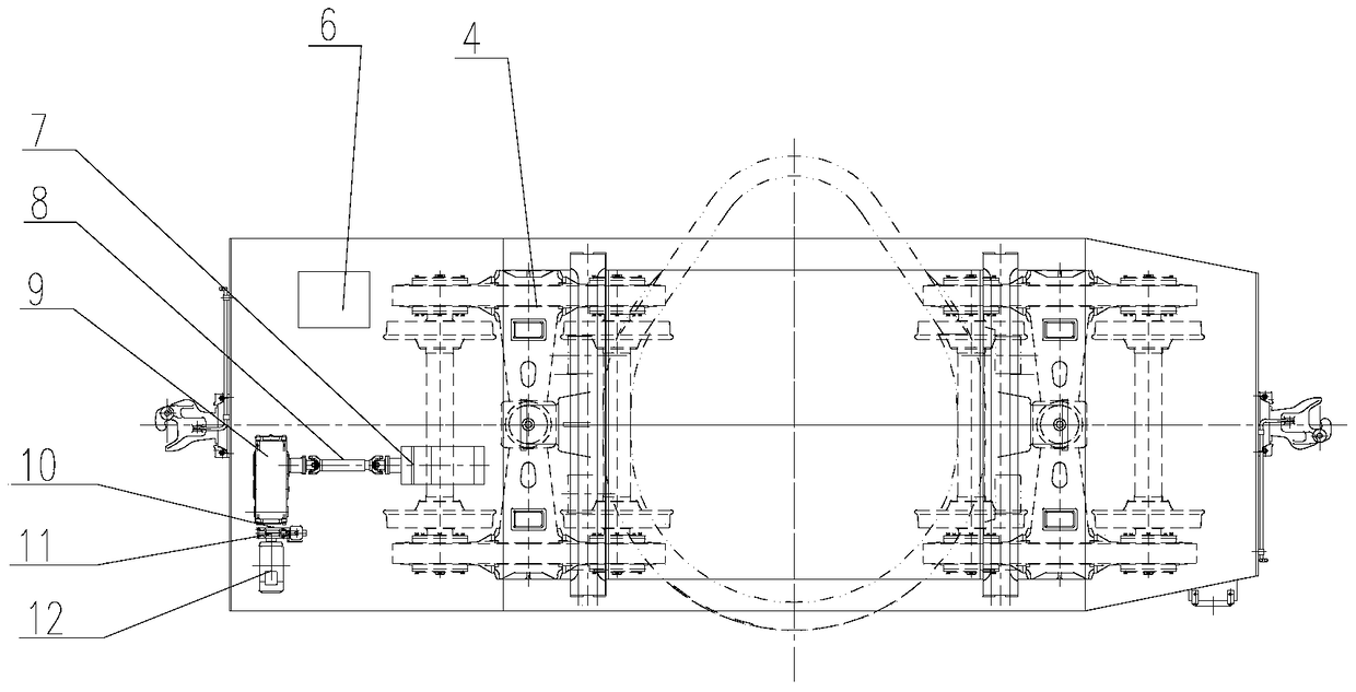
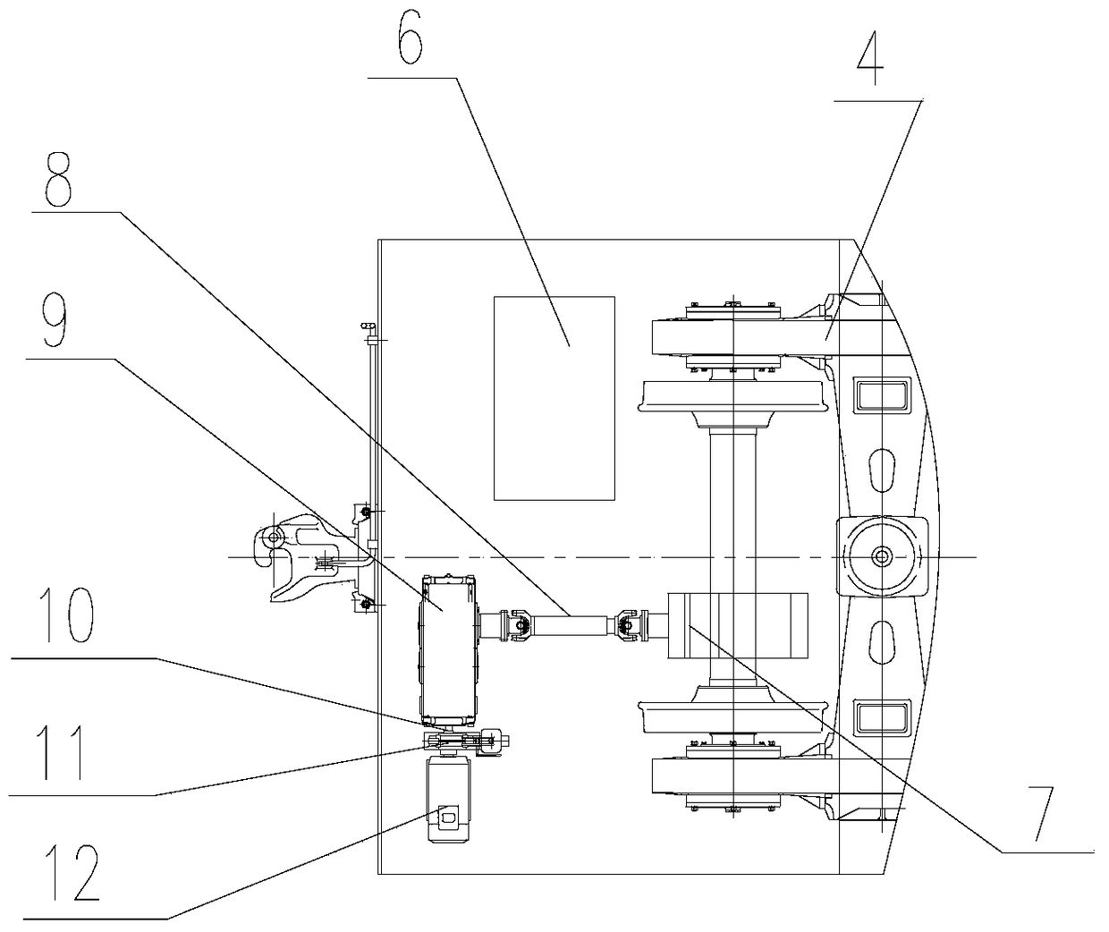
[0033] Such as Figure 1-Figure 6 As shown, the rail vehicle with a self-propelled bogie structure in Embodiment 1 includes two bogies 4 and a vehicle frame 13 installed above the two bogies 4 and connected in rotation with the two bogies 4 respectively. Such as figure 1 As shown, the two ends of the vehicle frame 13 are also provided with coupler buffer devices 5 respectively, which can realize two vehicles being connected or pulled by a locomotive when a failure occurs. Such as figure 1 , figure 2 and image 3 As shown, in this embodiment, each bogie 4 includes at least two axles 22, wherein one axle 22 is provided with a commutator 7 that drives it to rotate, and the axle 22 on which the commutator 7 is installed is a drive shaft. 221. One end of the vehicle frame 13 is provided with a drive system for driving the commutator 7, and a brake is also provided on one of the axles 22 or the drive system. The function of the drive system is to provide power for the entire ...

Embodiment 2

[0044] The difference between the second embodiment and the first embodiment lies in the difference of the driving system. Such as Figure 8 and Figure 9 As shown, the drive system of the self-propelled bogie structure rail vehicle of Embodiment 2 includes a diesel engine 171, and the transmission mechanism includes a second universal transmission mechanism 81, a hydraulic torque converter 92 and a third universal transmission mechanism 82; The diesel engine 171 is connected to the hydraulic torque converter 92 through the second universal transmission mechanism 81 , and the hydraulic torque converter 92 is connected to the commutator 7 through the third universal transmission mechanism 82 . Both the second universal transmission mechanism 81 and the third universal transmission mechanism 82 include a transmission shaft and universal joints arranged at both ends of the transmission shaft. The brake is arranged on the commutator 7, and a friction plate is arranged on its out...

Embodiment 3

[0046] The difference between the third embodiment and the first embodiment lies in the difference of the driving system. Such as Figure 10 and 11 As shown, the drive system of the self-propelled bogie structure rail vehicle of embodiment three includes a diesel engine 171, a hydraulic pump 94, a hydraulic control valve group 51 and a hydraulic motor 85, and the hydraulic motor 85 is directly connected with the commutator 7; the diesel engine 171 drives the hydraulic pump 94 to rotate to compress the hydraulic medium. The flow direction and on-off of the hydraulic medium are controlled by the hydraulic control valve group 51. The hydraulic control valve group 51 is connected to the hydraulic motor 85 through the hydraulic hose 52 to drive the hydraulic motor 85 to rotate. The hydraulic motor 85 drives the commutator 7, so that the axle 22 rotates together with the wheels 21 to realize smooth running.

[0047] The hydraulic station 61 and the hydraulic control valve group 51...


PUM


Abstract

The invention discloses a rail vehicle with a self-propelled bogie structure, which comprises at least two bogies, a vehicle frame installed above the bogies and respectively rotatably connected to the bogies, and each of the bogies includes at least Two axles, at least one axle is provided with a commutator to drive it to rotate, one end of the frame is provided with a driving system for driving the commutator, and the self-propelled bogie structure rail vehicle is also provided with There are brakes to slow down and stop the vehicle. By adding a drive system, the invention can realize the self-propelled running of the vehicle with bogie structure, and can also tow other vehicles to run without traction locomotive, which solves the problem of driving power of the bogie vehicle on the short line and changes the bogie in the metallurgical industry The state in which structural vehicles are driven by locomotives. It not only solves the process layout problem on the short circuit, but also reduces the equipment cost, improves the utilization rate of the equipment, and creates considerable economic and social benefits.

Description

technical field [0001] The invention relates to a rail transport vehicle with a self-driving bogie structure for transporting molten iron and steel coils in the metallurgical industry and ores for mining enterprises. Background technique [0002] At present, the transportation of molten iron from the blast furnace to the converter in the metallurgical industry usually adopts rail vehicles with a bogie structure to transport by rail. The rail vehicle includes a torpedo tank car, a blast furnace molten iron tank car and a canned molten iron tank car. Because the line between the blast furnace and the converter is a combination of straight lines and curves, the vehicles are required to have a certain ability to pass through curves. Therefore, these rail vehicles are usually bogie structures. These rail vehicles generally have no power themselves. The traction power required for walking, and the braking force required for deceleration, parking, and parking all come from the tra...

Claims


Application Information

Patent Timeline
Patent Type & Authority Patents(China)
IPC IPC(8): B61C9/50B61C9/14B61F5/00
CPCB61C9/14B61C9/48B61F3/04
Inventor 王伟峰杨树新郝晓静杨凤民郁景民茹殿坤韩珍
Owner QINHUANGDAO QINYE HEAVY IND
Why Eureka
Try Eureka