Underground gasification jet nozzle

An underground gasification and nozzle technology, which is applied in coal gasification, underground mining, construction, etc., can solve the problems of open fire on the outer wall of the nozzle and pitting of burning coal particles, affecting industrialization needs, etc., to improve service life, prevent pitting, improve The effect of gas quality

Active Publication Date: 2015-07-08
ENN SCI & TECH DEV
View PDF5 Cites 0 Cited by
  • Summary
  • Abstract
  • Description
  • Claims
  • Application Information

AI Technical Summary

Problems solved by technology

[0004] In order to solve the technical problem that the outer wall of the existing nozzle is easily pitted by open flames and burning coal particles, which affects the needs of industrialization, the invention provides an underground gasification nozzle

Method used


Image

  • Underground gasification jet nozzle
  • Underground gasification jet nozzle
  • Underground gasification jet nozzle

Examples


Embodiment 1

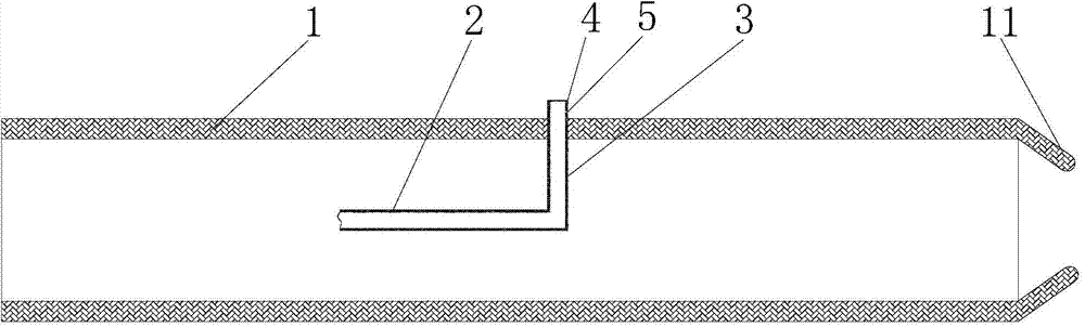
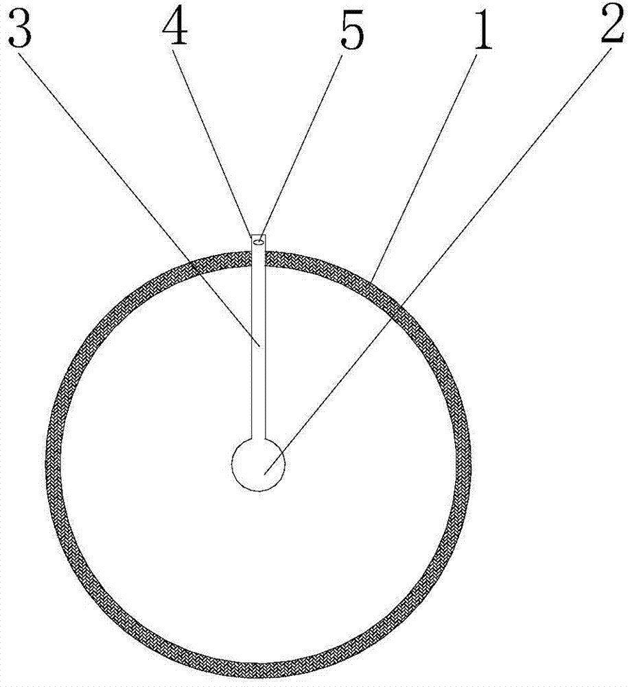
[0051] Such as figure 1 and figure 2 As shown, an underground gasification nozzle provided by Embodiment 1 of the present invention includes an outer pipe body 1, and a main water pipe 2 is arranged inside the outer pipe body 1; the main water pipe 2 is connected with a shunt pipe 3, and the shunt pipe 3 is provided with The water outlet part 4 on the outer wall of the pipe body 1; wherein, the water outlet part 4 is a tubular structure; the top of the water outlet part 4 is closed, and a first water outlet hole 5 is arranged on the top side wall of the water outlet part 4; the water outlet direction of the first water outlet hole 5 is biased outward The axial direction of the pipe body 1 forms any angle between 45° and 90° with the axial direction of the outer pipe body 1 .

[0052] This structural setting can make the water flow sprayed out of the first water outlet hole 5 contact the outer surface of the outer wall of the outer pipe body 1 as soon as possible, ensure the ...

Embodiment 2

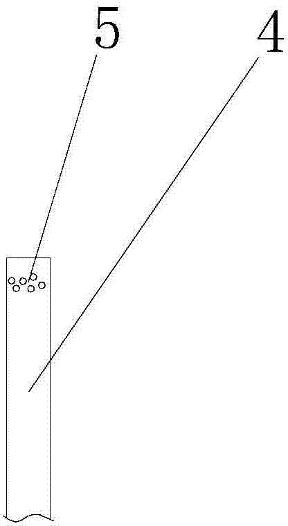
[0054] The main difference between the second embodiment of the present invention and the first embodiment of the present invention is that a plurality of first water outlet holes 5 are arranged on the top side wall of the water outlet part 4; image 3 As shown, the water outlet direction of each first water outlet hole 5 deviates from the axial direction of the outer tube body 1 and forms any angle between 45° and 90° with the axial direction of the outer tube body 1 . The other structures of the second embodiment are basically the same as those of the first embodiment. For details, reference may be made to the statement of the first embodiment above, and details are not repeated here.

Embodiment 3

[0056] The main difference between the third embodiment of the present invention and the first embodiment of the present invention is that the three branch pipes 3 connected by the main water pipe 2, such as Figure 4 As shown, each branch pipe 3 is provided with a water outlet 4 protruding from the outer wall of the outer pipe body 1; wherein, the water outlet 4 is a tubular structure; the top of the water outlet 4 is closed, and a first water outlet is arranged on the top side wall of the water outlet 4 Hole 5; the water outlet direction of the first water outlet hole 5 is biased toward the axial direction of the outer tube body 1 and forms any angle between 45° and 90° with the axial direction of the outer tube body 1 .

[0057] As another option, the main water pipe 2 can also be connected with two, four or five branch pipes 3, and a plurality of first water outlet holes 5 can also be arranged on the top side wall of the water outlet part 4.

[0058] The other structures o...


PUM


Abstract

The invention discloses an underground gasification jet nozzle. The underground gasification jet nozzle comprises an outer pipe body, wherein a main water pipe is arranged in the outer pipe body and is connected with a water outlet module for spraying water towards the outer surface of the outer pipe body. The outer pipe body is directly subjected to water spraying for cooling, and meanwhile water can further enter a gasification zone to improve gas quality. Even if fiery burned coal granules fall onto the surface of the outer pipe in the gasification process, water flow sprayed out of the water outlet module can be also cooled, the jet nozzle is prevented from being burned down by open fire or burned coal granules, the service life of the jet nozzle is prolonged, and the underground gasification jet nozzle meets the industrial requirement.

Description

technical field [0001] The invention relates to the field of coal gasification, in particular to an underground gasification nozzle. Background technique [0002] During the underground gasification process, the nozzle of the gasification agent injection device and the wall of the oil pipe near the nozzle nozzle will be severely corroded and tempered. Among them, the reaction is more violent in the gasification process with high oxygen-enriched concentration, and the burning coal particles will fall near the nozzle and the surface of the nozzle. In the event of nozzle burnout, the nozzle needs to be lifted to the ground for maintenance, which means that the gas production will be stopped, and the rear synthesis system will also be stopped. In the industrial production process, this will cause losses of hundreds of thousands or millions of yuan. . [0003] In order to improve the service life of the nozzle and ensure the safety of coiled tubing gasification operation, water...

Claims


Application Information

Patent Timeline
Patent Type & Authority Applications(China)
IPC IPC(8): E21B43/295
CPCE21B43/295
Inventor 姚凯李金国刘清宇
Owner ENN SCI & TECH DEV
Why Eureka
Try Eureka