Ball screw transmission device

A transmission device and ball screw technology, applied in the direction of transmission device, transmission device parts, transmission elements, etc., can solve the problems of many processing procedures, difficult processing, complex structure, etc., to reduce volume and weight, simple and reliable assembly, and transmission. Efficient effect

Inactive Publication Date: 2015-07-08
洪劲松
View PDF6 Cites 8 Cited by
  • Summary
  • Abstract
  • Description
  • Claims
  • Application Information

AI Technical Summary

Problems solved by technology

[0005] 1. Complex structure;
[0006] 2. In order to carry a high load, the internal circulation is adopted, and there are many processing procedures, especially the reverse through hole for the circular rolling of the steel ball is required to ensure the infinite circulation of the steel ball, the structure is complicated, and the size of the nut becomes large;
[0007] 3. In addition to the complexity of some screw nuts, the outer circle also needs to have gears or other connecting devices that cooperate with transmission, which makes the complex processing itself more difficult and unstable;
[0008] 4. Since the raceway is a continuous circulation transmission of balls, in addition to bearing the extrusion of the screw rod and nut, the circulating balls also contact and squeeze the front and rear balls, which hinders the smooth circular rolling of the balls, and is prone to friction and heat. A large number of balls are required, and the noise is large when rotating at a high speed. In the process of no or very little clearance when the head and tail steel balls are loaded, it is necessary to have a very high concentricity between the screw and the nut, and the low concentricity will lead to Stuck; some non-concentric positions will wear out faster and life will be reduced
This greatly reduces the efficiency of the ball screw drive, and the transmission efficiency is greatly reduced;
[0009] 5. In order to ensure the infinite circulation of the balls, the space required is large, the weight is high, and it is difficult to make small;
[0010] 6. In order to achieve the rolling of the balls in the raceway, it is necessary to add a reverser, which is troublesome to assemble and expensive; it is inconvenient to maintain

Method used


Image

  • Ball screw transmission device
  • Ball screw transmission device
  • Ball screw transmission device

Examples


Embodiment 1

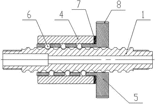
[0037] Such as figure 1 , image 3 , Figure 6 and Figure 7 As shown, a ball screw transmission device includes a screw rod 1 and a transmission assembly; the transmission assembly includes 4 nut outer sets and a cage 5, the inner surface of the nut sleeve 4 is processed into a smooth surface 41, and the nut sleeve 4 is installed on the outer circular surface of the cage 5, the inner wall of the nut jacket 4 is not provided with a raceway, and the smooth inner wall restricts the radial movement of the steel ball 6, so that the steel ball 6 forms a gap between the screw rod 1, the cage 5 and the nut jacket 4. A relatively closed space with a certain gap produces circular rolling; the nut jacket 4 is easy to process, and the requirements for processing equipment are greatly reduced; the cage 5 is processed with through holes 51, which can be evenly arranged, and the corresponding through holes 51 after the cage 5 is unfolded The center distance A of the hole 51 is an in...

Embodiment 2

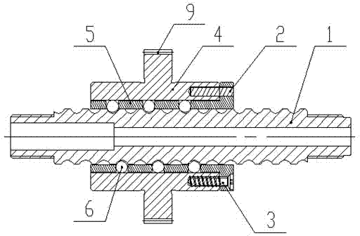
[0039] Such as figure 2 , Figure 4 , Figure 6 and Figure 7As shown, a ball screw transmission device includes a screw rod 1 and a transmission assembly; the transmission assembly includes a nut casing 4 and a cage 5, the inner surface of the nut casing 4 is processed into a smooth surface 41, and the nut casing 4 Installed on the outer circular surface of the cage 5, the inner wall of the nut jacket 4 is not provided with a raceway, and the smooth inner wall restricts the radial movement of the steel ball 6, so that the steel ball 6 forms a relative gap between the screw rod 1, the cage 5, and the nut jacket 4. A closed space with a certain gap produces circular rolling; the cage 5 is processed with a through hole 51, and the center distance A of the corresponding through hole 51 after the cage 5 is unfolded is an integral multiple of the pitch of the screw rod 1, and the nut sleeve 4 The smooth surface 41 and the upper surface of the cage 5 are fixed after being connec...

Embodiment 3

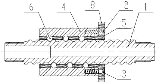
[0041] Such as Figure 5 , Figure 6 and Figure 7 As shown, a ball screw transmission device includes a screw rod 1 and a transmission assembly; the transmission assembly includes 4 nut outer sets and a cage 5, the inner surface of the nut sleeve 4 is processed into a smooth surface 41, and the nut sleeve 4 is installed on the outer circular surface of the cage 5, the inner wall of the nut jacket 4 is not provided with a raceway, and the smooth inner wall restricts the radial movement of the steel ball 6, so that the steel ball 6 forms a gap between the screw rod 1, the cage 5 and the nut jacket 4. A relatively closed space with a certain gap to produce circular rolling; the cage 5 is processed with a through hole 51, and the center distance A of the corresponding through hole 51 after the cage 5 is unfolded is an integer multiple of the pitch of the screw rod 1, and the nut is covered The smooth surface 41 of 4 and the upper surface of the cage 5 are fixed after being conn...


PUM


Abstract

The invention relates to a ball screw transmission device and belongs to the technical field of machines. The ball screw transmission device comprises a screw and a transmission assembly. The transmission assembly comprises a nut sleeve and a holder. The inner surface of the nut sleeve is machined to be a smooth surface. A through hole is formed in the holder. After the holder is unfolded, the corresponding through hole center distance is an integral multiple of a screw pitch. The smooth surface of the nut sleeve is connected with the upper surface of the holder and then fixed, a steel ball is arranged in the through hole, the through hole and a roller path of the screw are identical in position in a circulatory mode and then the transmission assembly is formed. A transmission gear is arranged on the transmission assembly. The screw penetrates through the holder and is connected with the steel ball through a roller path on the screw. By the adoption of the ball screw transmission device, switching between rotation motion and linear motion of the transmission assembly and the screw can be achieved, friction force is small, the transmission efficiency is high, noise is low, the service life is prolonged, cost is reduced, the applicability is high, labor is greatly liberated, and production efficiency is improved.

Description

Technical field [0001] The present invention is a mechanical technology field, especially involving a roller screw transmission device. Background technique [0002] The roller screw is the most commonly used transmission element in tool machinery and precision machinery. Its main function is to convert the rotation movement into a linear movement, or to convert the torque into axial repeated force. At the same time, it has high precision, reversibility and highFeatures of efficiency.Due to a small frictional resistance, the roller screws are widely used in various industrial equipment and precision instruments.Its significance is to change the bearings from sliding to rolling.At present, the high -end machinery field has basically replaced the sliding screws such as trapezoidal screws. [0003] At present, the rotation movement needs to be converted into a linear movement part of the low -end products. It still uses trapezoidal screws. The transmission efficiency of trapezoidal ...

Claims


Application Information

Patent Timeline
Patent Type & Authority Applications(China)
IPC IPC(8): F16H25/22
CPCF16H25/2204F16H57/042F16H2700/00
Inventor 洪劲松
Owner 洪劲松
Why Eureka
Try Eureka