
A kind of optical fiber array and its manufacturing method

A technology of optical fiber array and optical fiber, which is applied in the field of communication, can solve problems such as impracticability, and achieve the effect of simple production process and small size

Active Publication Date: 2017-11-10
GUANGXUN SCI & TECH WUHAN
View PDF4 Cites 0 Cited by
  • Summary
  • Abstract
  • Description
  • Claims
  • Application Information

AI Technical Summary

Problems solved by technology

Almost impossible to achieve with high fiber count

Method used


Image

  • A kind of optical fiber array and its manufacturing method
  • A kind of optical fiber array and its manufacturing method
  • A kind of optical fiber array and its manufacturing method

Examples


Embodiment Construction

[0038] In order to better understand the present invention, the structure and implementation of the present invention will be described in detail below in conjunction with specific examples and accompanying drawings.

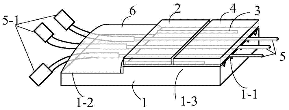
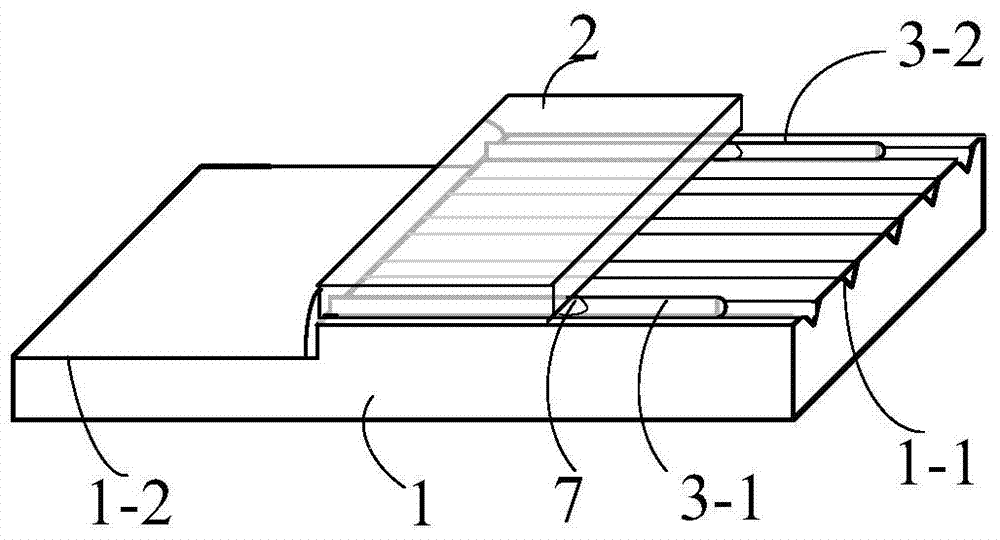
[0039] The optical fiber array of the present invention consists of a substrate for optical fiber positioning, a fiber threading cover for fiber threading, an auxiliary fiber supporting fiber threading cover, a fiber pressing cover for pressing optical fibers, and a multiple Root coupling optical fiber, and glue for fixing. One end of the base plate has one or more parallel positioning V-shaped grooves, and the horizontal spacing of the positioning V-shaped grooves is consistent with the horizontal spacing of the waveguide of the integrated chip, and is used to place the stripped optical fiber. There are two cover plates above the positioning V-shaped groove. One cover plate forms a positioning hole through the auxiliary fiber and the positioning V-shaped groove...


PUM


Abstract

The invention discloses an optical fiber array and a manufacturing method thereof. The optical fiber array comprises a substrate (1) and multiple coupling optical fibers (5). A first platform (1-2) and a second platform (1-3) are formed on the substrate (1) in a stepped mode, V-shaped locating grooves (1-1) of which the number is larger than or equal to that of the coupling optical fibers (5) are formed in the second platform (1-3), and the coupling optical fibers (5) are correspondingly arranged in the V-shaped locating grooves (1-1) and extend out of the substrate (1). The optical fiber array further comprises a fiber passing cover plate (2), an auxiliary locating device and a fiber pressing cover plate (4). The auxiliary locating device is arranged between the fiber pressing cover plate (4) and the second platform (1-3) and supports the fiber passing cover plate (2) so that through holes through which the coupling optical fibers (5) can pass can be formed between the fiber passing cover plate (2) and the V-shaped locating grooves (1-1) covered with the fiber passing cover plate (2). The optical fiber array manufactured through the method is small in size and easy to manufacture.

Description

technical field [0001] The invention relates to an optical fiber array and a manufacturing method thereof, belonging to the field of communication. Background technique [0002] The integrated planar optical waveguide chip can realize the combination of multiple optical functions into a single chip, which has high integration, small size and low cost, and is widely used in the field of optical devices. Such chips need to be optically connected when they are made into optical devices. The common method is to couple and align the optical fiber array with the integrated chip to realize the connection of the optical path. [0003] In order to ensure the precise positioning of the optical fiber, it is necessary to arrange multiple optical fibers in parallel on the substrate of the V-shaped groove with the function of fiber positioning when making the optical fiber array, and then clamp and fix the optical fiber in the V-shaped groove with a flat cover plate. The cover plate and ...

Claims


Application Information

Patent Timeline
Patent Type & Authority Patents(China)
IPC IPC(8): G02B6/12G02B6/13
CPCG02B6/3608G02B6/364
Inventor 宋琼辉朱虎凌九红杜巍马卫东
Owner GUANGXUN SCI & TECH WUHAN
Learn More