
LED light bulb construction and manufacture

a technology of led light bulbs and construction, applied in the direction of point-like light sources, semiconductor devices of light sources, light and heating apparatus, etc., can solve the problems of increasing electricity prices in industrialized nations, increasing electricity demand and fossil fuel consumption, and system incurring higher generation costs, so as to increase the lifetime, widespread availability and cost effectiveness of wireless technology

Active Publication Date: 2022-01-11
SMARTBOTICS
View PDF11 Cites 0 Cited by
  • Summary
  • Abstract
  • Description
  • Claims
  • Application Information

AI Technical Summary

Benefits of technology

This approach reduces production costs, improves thermal management, and allows for automated assembly, resulting in LED bulbs that mimic the appearance and illumination pattern of incandescent bulbs while offering extended lifespan and energy efficiency.

Problems solved by technology

These include the recognition of global warming regardless of cause; industrialization of third world countries creating huge increases in electricity demand and fossil fuel consumption, with the obvious economic and pollution problems associated; and increasing electricity prices within industrialized nations as overburdened electrical grid systems incur higher generation costs and struggle to match demand.
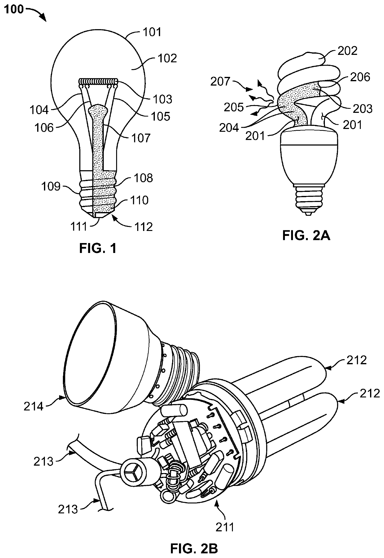
All forms of incandescent light bulbs waste a substantial percentage of the electricity they consume in the generation of heat, rather than light.
However, while CFLs significantly reduce the electricity consumption compared with an equivalent (lumens) lighting level of incandescent bulbs, they have drawbacks such as the “warm up” time they require before producing their full light output, the harsh / cold (spectrally deficient) light they emit, and the use of toxic mercury in the manufacturing process causing environmental handling and disposal problems.
While LED light bulbs are currently more expensive than incandescent or CFL bulbs, they have much longer operating lifetimes. LED light bulbs have typical operational lifetimes of 30,000 hours or more, compared with CFLs at around 8,000 hours and incandescent light bulbs at around 1,000 hours.
The initial adoption of LED light bulbs has been slow due to their high price as a result of costly manufacturing (passed on to consumers) when compared to incandescent and CFL bulbs, and the expensive and complex thermal management components required to dissipate the heat generated and maintain the electronic components in the bulb within their operational range.
However, LED light bulbs are typically assembled in the same manner as incandescent and CFL light bulbs and these processes are not well suited to the assembly processes usually employed for printed circuit board (PCB) assemblies such as those used in high volume consumer electronics and the like.
This connectivity method is highly inefficient, potentially unreliable, labor intensive, and an impediment to automated assembly.
Moreover, like all semiconductor devices, LEDs generate significant heat during operation, and will eventually be damaged or destroyed if the heat buildup is not constrained.
This leads to high point-source heat generation from the LEDs, and poses severe heat dissipation issues.
However, when considering integrating additional high technology capabilities into a light bulb using semiconductors, for instance, heat becomes of paramount concern.
Typically, early generation LEDs used in LED-based lights were either inefficient and / or chosen for the lowest possible cost, and therefore they generated significant heat.
Hence, LED bulbs typically required large expensive heatsinks and complex thermal management to dissipate the heat generated to maintain the electronic components in the bulb within their operational range.
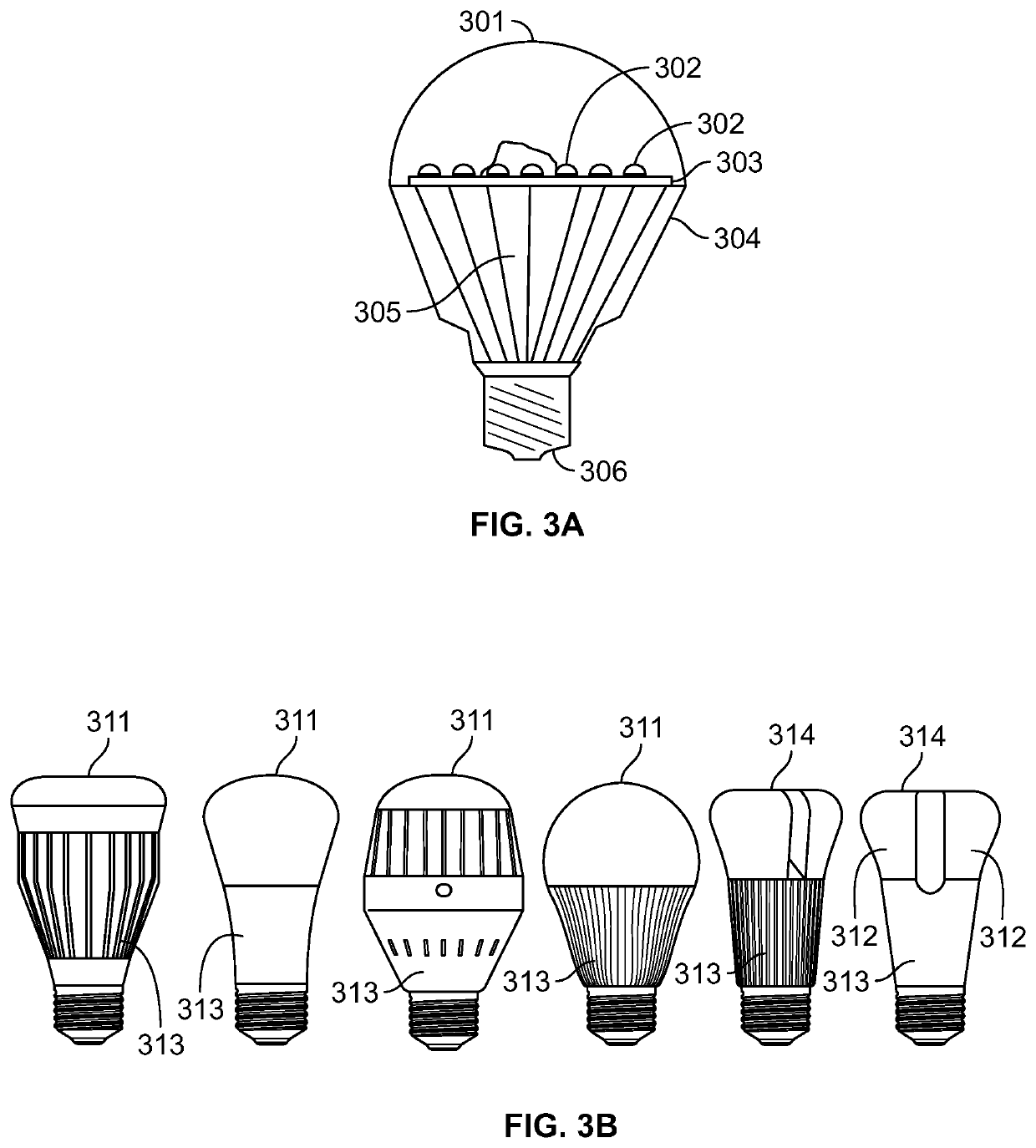
Such heatsinks are mounted on the exterior of the bulb near the base, rendering this area unusable for illumination from the bulb.
This then reduces the overall illumination effect of the bulb, especially when the bulb is required to replicate the broad, even, spherical radiated light pattern of an incandescent light bulb.
This also tends to make LED bulbs less aesthetically appealing and much heavier than the bulbs they replace, and in some case makes them unsuitable for some existing lighting enclosures and fittings.

Method used


Image

  • LED light bulb construction and manufacture
  • LED light bulb construction and manufacture
  • LED light bulb construction and manufacture

Examples


Embodiment Construction

[0034]To provide an overall understanding of the innovative aspects of the subject matter, certain illustrative embodiments are described; however, one of ordinary skill in the art would understand that the embodiments described herein may be adapted and modified as is appropriate for the specific application being addressed, and that alternative implementations may be employed to better serve other specific applications, and that such additions and modifications will not depart from the overall scope hereof.

[0035]In the following detailed description, terminology had been adopted to describe aspects of the disclosure. Since this disclosure defines a new class of lighting product, some new terms and phrases have been defined, such that a consistent nomenclature is used throughout this description. Other descriptive terms and phrases are used to convey a generally agreed upon meaning to those of ordinary skill in the art, unless a different definition is given in this specification. ...


PUM


Abstract

An LED light bulb with integrated power supply, and which may incorporate integrated communications and processing functions. The LED light bulb is designed to be efficiently manufactured in mass quantities using automated assembly techniques, and is constructed to exhibit the spatial light pattern of a regular incandescent bulb as closely as possible. Where communications and processing functions are integrated, the LED light bulb is able to communicate via wireless communications to a mobile phone, notebook, tablet, or other computing device.

Description

CROSS REFERENCE TO RELATED APPLICATIONS[0001]This application is a continuation in part application of, and claims priority to, U.S. Non-Provisional application Ser. No. 16 / 575,164 entitled “LED Light Bulb Construction and Manufacture,” filed on 18 Sep. 2019, now U.S. Pat. No. 10,760,196, which is a continuation application of, and claims priority to, U.S. Non-Provisional application Ser. No. 16 / 105,705 entitled “LED Light Bulb Construction and Manufacture,” filed on 20 Aug. 2018, now U.S. Pat. No. 10,465,857, which is a continuation application of, and claims priority to, U.S. Non-Provisional application Ser. No. 15 / 465,437 entitled “LED Light Bulb Construction and Manufacture,” filed on 21 Mar. 2017, now U.S. Pat. No. 10,088,112, which is a continuation application of, and claims priority to, U.S. Non-Provisional application Ser. No. 14 / 210,018 entitled “LED Light Bulb Construction and Manufacture,” filed on 13 Mar. 2014, now U.S. Pat. No. 9,644,799, which claims priority to U.S. ...

Claims


Application Information

Patent Timeline
Patent Type & Authority Patents(United States)
IPC IPC(8): F21K9/238H05B47/19F21V23/00F21K9/23F21K9/232F21K9/235F21K9/237F21V23/06F21V23/04F21Y101/00F21V23/02F21Y115/10F21Y107/40F21V29/77F21V3/06F21V3/02F21V17/10F21V3/00
CPCF21K9/238F21K9/23F21K9/232F21K9/235F21K9/237F21V3/02F21V3/061F21V17/101F21V23/005F21V23/045F21V23/06F21V29/77H05B47/19F21V3/00F21V23/006F21V23/02F21Y2101/00F21Y2107/40F21Y2115/10H05K1/145H05K3/366H05K2201/10106H05B47/1985
Inventor CRAYFORD, IANCOFFEY, KELLYEDWARDS, JON
Owner SMARTBOTICS
Learn More