
Direct voltage splitting circuit supporting multi-level technology

A DC voltage and voltage dividing circuit technology, applied in the direction of irreversible DC power input conversion to AC power output, AC power input conversion to DC power output, electrical components, etc., can solve voltage unit voltage breakdown, capacitor unit Problems such as uneven voltage and uneven voltage, to prevent breakdown by withstand voltage and ensure voltage equalization

Inactive Publication Date: 2015-07-08
杜心林
View PDF4 Cites 1 Cited by
  • Summary
  • Abstract
  • Description
  • Claims
  • Application Information

AI Technical Summary

Problems solved by technology

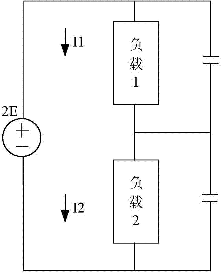
Since the first capacitor C1 and the second capacitor C2 share the DC voltage 2E together, during the load operation, when the voltages of the two loads are not equal, their currents are also not equal, as shown in the figure, assuming that the first load unit When a current I1 is greater than the second current I2 of the second load unit, the voltage of the first capacitor C1 drops, and the voltage of the second capacitor C2 rises; assuming that the first current I1 of the first load unit is smaller than the second current I2 of the second load unit When , the voltage of the first capacitor C1 rises, and the voltage of the second capacitor C2 drops, which will cause the voltage of the two capacitor units to be uneven
Therefore, the key problem in the DC voltage divider circuit of multi-level technology is the withstand voltage of the device. Due to the uneven load voltage, the voltage of different voltage units that provide the load voltage is uneven, and it is likely that the withstand voltage of the voltage unit Wear, affecting the reliable operation of medium and high voltage frequency conversion speed control equipment

Method used


Image

  • Direct voltage splitting circuit supporting multi-level technology
  • Direct voltage splitting circuit supporting multi-level technology
  • Direct voltage splitting circuit supporting multi-level technology

Examples


Embodiment Construction

[0030] In order to make the object, technical solution and advantages of the present invention clearer, the present invention will be further described in detail below with reference to the accompanying drawings and examples.

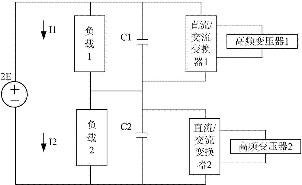
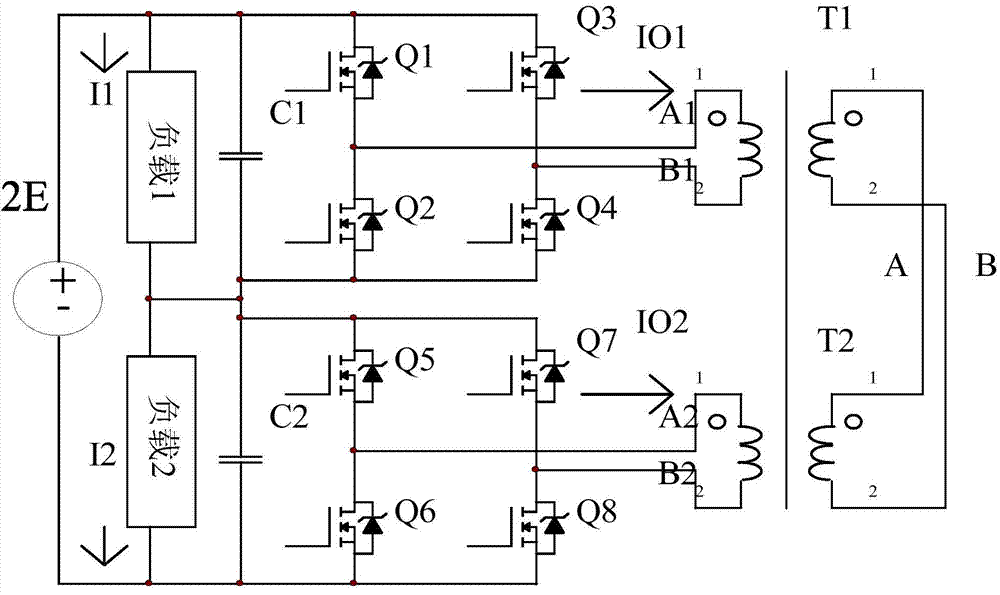
[0031] It can be seen from the background technology that in the DC voltage equalizing circuit of multi-level technology, the cause of voltage breakdown of voltage units is that the energy of different voltage units is different due to the unbalanced load voltage of different voltage units. deviation. Therefore, in order to solve this problem, in the DC voltage equalizing circuit of the multi-level technology in the embodiment of the present invention, for two or more voltage units used to share the DC voltage, each voltage unit is connected to a DC / AC converter and a high-frequency transformer, in which the high-voltage inverters of different voltage units have the same structure, the primary side is connected with the same polarity, and the secondary ...


PUM


Abstract

The invention discloses a direct voltage splitting circuit supporting the multi-level technology. According to a direct voltage equalizing circuit in the multi-level technology, each of two or more voltage units used for sharing direct voltage is connected with a direct current / alternating current exchanger and a high-frequency transformer, the high-frequency transformers of the different voltage units are the same in structure, primary side connection polarities are the same, and auxiliary side same polarities are connected in parallel. Thus, when load voltages of the different voltage units are different, the different voltage units can transmit energy to the different high-frequency transformers through the direct current / alternating current exchangers respectively, energy transmission is carried out between the different high-frequency transformers, and therefore voltage equalizing of the different voltage units can be achieved. Thus, when the load voltage of the different voltage units deviates, voltage equalizing of the voltage units is guaranteed, and withstand voltage breakdown is prevented.

Description

technical field [0001] The invention relates to power electronics technology, in particular to a DC voltage divider circuit supporting multi-level technology. Background technique [0002] The energy-saving effect of medium and high voltage frequency conversion speed regulation is becoming more and more significant, and with the increasing awareness of energy saving and emission reduction, medium and high voltage frequency conversion speed regulation technology has developed rapidly. In the medium and high voltage frequency conversion technology, with the continuous improvement of the withstand voltage level of power devices, the use of multi-level technology for DC voltage input has great potential for development. In the multi-level technology, the DC voltage input unit is generally composed of multiple voltage units, and after the DC input voltage is divided, they are respectively provided to different loads. Currently, multiple voltage units can provide multiple capacit...

Claims


Application Information

Patent Timeline
Patent Type & Authority Applications(China)
IPC IPC(8): H02M7/48H02M1/32
CPCH02M7/48H02M1/32H02M7/483
Inventor 杜心林
Owner 杜心林
Learn More