
Synchronous control system and method for multiple motors in CT machine

A synchronous control and multi-motor technology, which is applied in the direction of controlling multiple DC motors, can solve problems affecting the working performance and service life of CT machines, affecting the accuracy of the stop position of the scanning bed, and affecting the imaging quality of CT images, etc., achieving low cost, Precise stop position and prolong service life

Active Publication Date: 2015-07-08
SAINUO WEISHENG SCI & TECH BEIJING
View PDF4 Cites 5 Cited by
  • Summary
  • Abstract
  • Description
  • Claims
  • Application Information

AI Technical Summary

Problems solved by technology

However, if the synchronous motion control of the two motors on both sides of the frame is not done well, it will seriously affect the working performance and service life of the CT machine
In addition, it will also affect the accuracy of the stop position of the scanning table during the movement process, thereby affecting the quality of CT image imaging, and thus affecting the diagnostic results

Method used


Image

  • Synchronous control system and method for multiple motors in CT machine
  • Synchronous control system and method for multiple motors in CT machine
  • Synchronous control system and method for multiple motors in CT machine

Examples


Embodiment Construction

[0035]The following will clearly and completely describe the technical solutions in the embodiments of the present invention with reference to the accompanying drawings in the embodiments of the present invention. Obviously, the described embodiments are only some, not all, embodiments of the present invention. Based on the embodiments of the present invention, all other embodiments obtained by persons of ordinary skill in the art without creative efforts fall within the protection scope of the present invention.

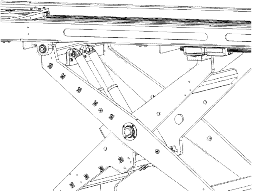
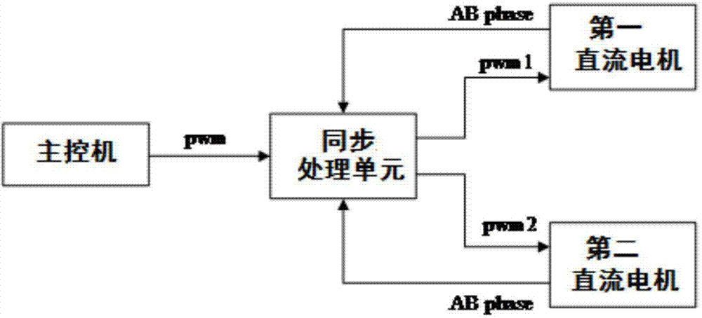
[0036] The present invention discloses a multi-motor synchronous control system in a CT machine, which includes: at least two DC motors installed on both sides of the scanning bed; a main control unit for sending PWM modulation codes; a synchronous processing unit for synchronous control. The structure of the scanning bed in the system is as follows: figure 1 shown.

[0037] In a specific embodiment, two DC motors are installed on both sides of the scanning bed, a...


PUM


Abstract

The invention relates to a synchronous control system for multiple motors in a CT machine. The synchronous control system comprises at least two direct current motors arranged on the two sides of a scanning bed, a main control computer used for sending PWM modulation codes and a synchronous processing unit used for conducting synchronous control. The invention further relates to a synchronous control method for the multiple motors in the CT machine. According to the method, at least two direct current motors are utilized to push the scanning bed to lift and conduct synchronous control, and inconformity of the stretching-out length of two pushing rods generated due to mechanical installation and inconformity of motion characteristics of all the motors can be compensated; at least two direct current motors are utilized to push a rack to conduct inclined motion and conduct synchronous control at the same time, and inconformity of the stretching-out length of the two pushing rods generated due to mechanical installation and inconformity of motion characteristics of all the motors can be compensated. According to the synchronous control system and method, synchronous motion of the scanning bed in the CT machine and the double motors of the rack is controlled, the scanning bed and the rack can conduct accurate off-position in the motion process, and thus the service life of products is prolonged.

Description

technical field [0001] The invention relates to the technical field of multi-motor synchronous control, in particular to a multi-motor synchronous control system and method applied in a CT machine. Background technique [0002] In high-precision, high-safety, heavy-duty systems such as medical care and CNC machine tools, multi-motor motion synchronization control is a very important core issue. The synchronization of multi-motor motion directly affects the reliability and service life of CT machines. [0003] With the development of numerical control technology, it is more frequent to use multiple motors in one system to drive heavy load systems for movement. For example, for the scanning bed in the CT machine, the scanning bed of the traditional CT machine uses a motor and a booster spring to start the up and down movement of the scanning bed. This traditional method of using a single motor and a booster spring has technical requirements and The production process is very ...

Claims


Application Information

Patent Timeline
IPC IPC(8): H02P5/68
Inventor 屈善新周宇董连海刘华湘
Owner SAINUO WEISHENG SCI & TECH BEIJING
Learn More