All-round community security and protection system

A security system, a comprehensive technology, applied in the field of community security systems, can solve problems such as difficult to find intruders

Inactive Publication Date: 2015-07-08
四川金石科技有限公司
View PDF6 Cites 8 Cited by
  • Summary
  • Abstract
  • Description
  • Claims
  • Application Information

AI Technical Summary

Problems solved by technology

Furthermore, there is another type of camera that is manually controlled by remote workers to automatically patrol the side area. However, when the thief is in a blind spot, it is difficult for remote workers to find intruders outside the line of sight.

Method used


Image

  • All-round community security and protection system

Examples


Embodiment 1

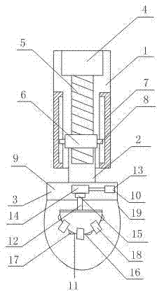
[0015] Such as figure 1 As shown, an all-round community security system includes a support rod 1, a connecting rod 2 slidingly arranged in the supporting rod 1, and a monitoring system 3 fixed at the lower end of the connecting rod 2; the supporting rod 1 is a cavity structure, and also includes The motor 4 fixed on the top plate of the support rod 1 also includes a screw mandrel 5 connected to the output shaft of the motor 4 and a nut 6 that is sleeved on the screw mandrel 5 and cooperates with the screw mandrel 5, and also includes two screws arranged on the inner wall of the support rod 1 The slide rail 7 on the side and the slide block 8 connected to the two ends of the nut 6, the slide block 8 is slidably arranged in the slide rail 7; the connecting rod 2 is a cavity structure and its upper end is fixed on the lower surface of the nut 6, and the screw rod The lower part of the connecting rod 2 is inserted into the cavity structure of the connecting rod 2; the monitoring ...

Embodiment 2

[0018] In this embodiment, on the basis of Embodiment 1, the camera 11 includes a hemisphere 16, an infrared probe 17 evenly arranged on the hemisphere 16, and at least three cameras 18 evenly arranged on the bottom of the hemisphere, and the connecting rod 12 The other end is fixed on the central position of the hemisphere 16.

[0019] In the present embodiment, the infrared probe 17 that is evenly arranged on the surface of the hemisphere 16 monitors objects that invade into the tested area. Driven by the driving force, the intruders are monitored at 360° without dead angle.

Embodiment 3

[0021] On the basis of Embodiment 1 or Embodiment 2, this embodiment further includes a protective cover 19 fixed at the bottom of the transition section 9 , and the camera device 11 is arranged in the protective cover 19 .

[0022] In this embodiment, the protective cover 19 plays a role of protecting the camera device 11, preventing the camera device 11 from being exposed to wind and rain.


PUM


Abstract

The invention discloses an all-round community security and protection system. The all-round community security and protection system comprises a supporting rod, a connecting rod arranged in the supporting rod in a sliding mode and a monitoring system fixed to the lower end of the connecting rod. The all-round community security and protection system further comprises a motor, a screw rod, a nut, slide rails and slide blocks, wherein the motor is fixed to the top plate of the supporting rod, the screw rod is connected with an output shaft of the motor, the screw rod is sleeved with the nut, the nut is matched with the screw rod, the slide rails are arranged at the two sides of the inner wall of the supporting rod, the slide blocks are connected to the two ends of the nut, and the slide blocks are arranged in the slide rails in a sliding mode. The monitoring system comprises a transition section fixed on the lower end of the connecting rod and a regulation device arranged in the transition section, and the transition section is of a cavity structure with a long-strip hole formed in the lower surface; the monitoring system further comprises a camera device and a connecting bar penetrating through the long-strip hole to fix the camera device onto the regulation device. In the all-round community security and protection system, the screw rod and the nut are arranged to enable the monitoring system to move up and down, and the regulation device enables the camera device to achieve 360-degree no dead corner monitoring.

Description

technical field [0001] The invention relates to a monitoring system, in particular to an all-round community security system. Background technique [0002] Existing cameras can rotate 360° left and right, and 90° up and down, and can basically monitor from all angles without dead angles. avoid. Furthermore, there is another type of camera that is manually controlled by a remote worker to automatically patrol the side area. However, when a thief is in a blind spot, it is difficult for the remote worker to find intruders outside the line of sight. Contents of the invention [0003] In order to solve the problem that existing cameras have monitoring blind spots and it is difficult to find intruders outside the line of sight, the present invention provides an all-round community security system. [0004] Technical scheme of the present invention is as follows: [0005] An all-round community security system, including a support rod, a connecting rod slidingly arranged in th...

Claims


Application Information

Patent Timeline
IPC IPC(8): H04N7/18
Inventor 彭小川
Owner 四川金石科技有限公司
Why Eureka
Try Eureka