Autoinjector

An automatic injector, automatic injection technology, applied in the direction of automatic injector, syringe, hypodermic injection device, etc., can solve the problems of unsatisfactory, the solution is not safe and reliable, etc.

Active Publication Date: 2015-07-08
APTAR FRANCE SAS
View PDF29 Cites 9 Cited by
  • Summary
  • Abstract
  • Description
  • Claims
  • Application Information

AI Technical Summary

Problems solved by technology

Since the system is then dependent on the user himself, who in some cases may be disturbed or debili

Method used


Image

  • Autoinjector
  • Autoinjector
  • Autoinjector

Examples


Embodiment Construction

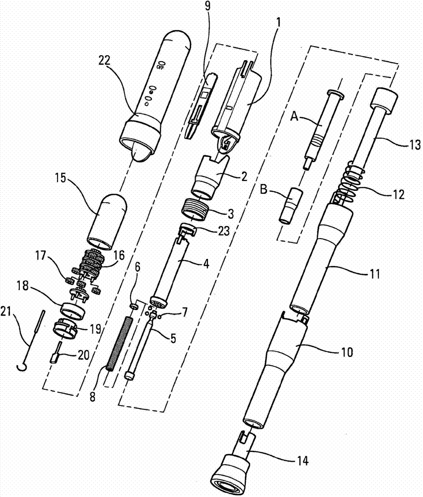
[0083] In the following, the auto-injector will be described with reference to different variants of two advantageous embodiments of the auto-injector. The first implementation is Figure 1 to Figure 46 shown above, the second embodiment is Figures 47 to 74c shown above. It should be noted, however, that an auto-injector, being a complex instrument, includes multiple modules for performing various functions. These different modules can be used individually and independently of each other without necessarily being combined with other modules, and can be used in particular in auto-injectors of shapes other than those shown in the drawings.

[0084] refer to figure 1, the different components of the auto-injector according to the first advantageous embodiment are shown exploded. In this first embodiment, in the order of the reference numbers, the autoinjector has: a central body 1 , a control ring 2 , a piercing spring 3 , a control sleeve 4 , a piston rod 5 , a bearing head...


PUM


Abstract

Autoinjector having a pre-filled syringe, a piston rod (1005), an injection spring (1008), a movable element (1004; 1006), an acoustic and/or tactile indicating device (1500) having a key (1121), said key having a shaft part (1120), which extends inside the piston rod (1005), and a head part (1122), said movable element having at least one deformable tab (1510; 1520), said piston rod (1005) exerting traction on said head part (1122) via said shaft part (1121) of said key (1120) at the end of injection, thereby permitting a radial deformation of said at least one deformable tab and an axial movement of said movable element under the effect of said injection spring (1008), said movement generating an acoustic and/or tactile indication for the user.

Description

technical field [0001] The present invention relates to automatic injectors. Background technique [0002] Autoinjectors are well known in the art. The main purpose of these devices is to achieve automatic injection of the contents of a syringe into a patient. Various systems exist for automating the insertion of a needle into a patient and the injection of a fluid formulation contained in a syringe. Auto-injectors are relatively complex devices that should meet a certain number of limitations for safety and reliability. The robustness, ease of handling and ease of use for the user of the device are also important factors. Also, since most of these auto-injectors are disposable, production and assembly costs should also be considered. [0003] There are many auto-injectors on the market, however, they all have a certain number of defects. [0004] Therefore, in order to avoid untimely triggering of the auto-injector, eg during transport or storage, the device should hav...

Claims


Application Information

Patent Timeline
IPC IPC(8): A61M5/20A61M5/315A61M5/00
CPCA61M5/3204A61M2205/3368A61M2205/581A61M2005/2086A61M5/326A61M2205/582A61M2205/584A61M2005/206A61M2205/3327A61M5/2033A61M5/20A61M2005/2013A61M5/3157A61M2005/3125A61M5/3272A61M2005/2073A61M5/31511A61M2005/2006A61M2005/31518A61M2205/58
Inventor D·法比恩A·曼森卡尔M·瓦尔特
Owner APTAR FRANCE SAS
Why Eureka
Try Eureka