
Infrared photography device and infrared photography method

An infrared photography and infrared thermal imaging technology is applied in the fields of infrared processing devices and infrared photographing devices, which can solve the problems that users are not easy to understand the subject, cannot correspond to the subject, and miss shooting, etc. Improved, easy-to-use effects

Active Publication Date: 2019-11-29
MISSION INFRARED ELECTRO OPTICS TECH
View PDF9 Cites 0 Cited by
  • Summary
  • Abstract
  • Description
  • Claims
  • Application Information

AI Technical Summary

Problems solved by technology

[0007] Since the application of thermal image detection technology, there is no suitable means to conveniently realize the information prompt of the subject, and users are often confused during shooting. Those skilled in the art have been trying to solve this problem. Like a shooting device, in the shooting of power lines, it can prompt GPS prompt information; but it is not easy for users to understand the specific subject to be photographed through GPS information; and there are dense multiple subjects in the same place and need to be separated When shooting, it cannot correspond to a specific subject
The above-mentioned prior art does not solve the problem that it is easy to miss shooting, etc. How to guide users to take infrared thermal image shooting is a difficult problem

Method used


Image

  • Infrared photography device and infrared photography method
  • Infrared photography device and infrared photography method
  • Infrared photography device and infrared photography method

Examples


Embodiment approach

[0093] One embodiment, based on the subject information stored in the information storage unit, query to obtain keywords of attribute information of specified attributes in the subject information, and determine the keywords obtained from the query as keywords related to sorting;

[0094] In addition, based on the subject information and keyword query conditions stored in the information storage unit, the keyword of the attribute information of the specified attribute in the subject information that meets the keyword query condition can be queried, and the keyword obtained from the query can be determined. is a keyword related to sorting;

[0095] In addition, pre-stored keywords can also be selected by users, and then the keywords selected by users are determined as keywords related to sorting;

[0096] In addition, by determining the keyword attribute, the keyword matching the keyword attribute can be determined as a keyword related to the sorting; for example, when the obje...

Embodiment 2

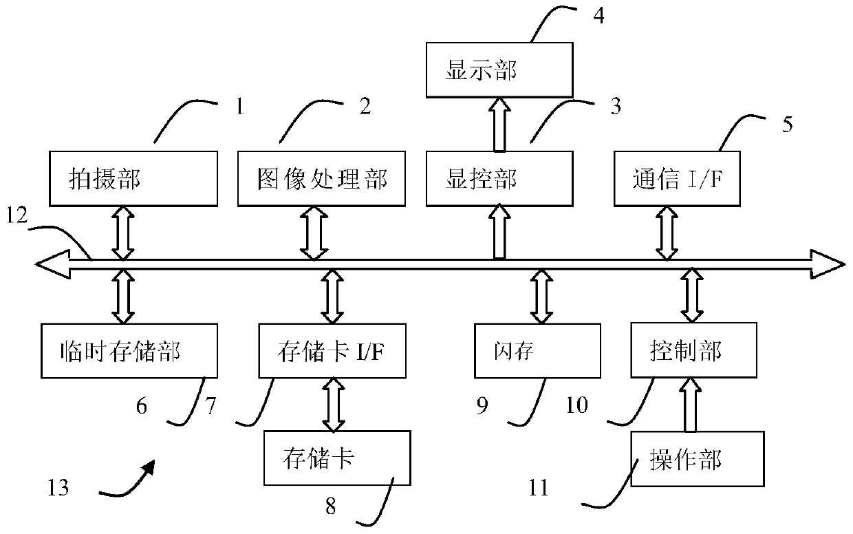
[0141] This embodiment is with figure 1 In the shown thermal imaging device 13 with the same structure, in the flash memory 9, a control program for setting filter conditions and a control program for determining (included in the shooting task) subject information are stored according to the filter conditions, so that the user can control the Figure 11 The scene where infrared detection is performed on electric equipment in equipment area 1 (1101), equipment area 2 (1102), and equipment area 3 (1103) in substation 1 as shown in is an example. Unlike embodiment 1, the user puts the The shooting task is decomposed into multiple subtasks through filter conditions, and then the subject information in the subtasks is sorted before shooting. refer to Figure 12 - Figure 17 This embodiment will be described.

[0142] In step S201, the control unit 10 implements its control and continuously monitors whether the user selects the information mode through the operation unit 11, and ...

Embodiment 3

[0172] This embodiment is with figure 1 In the shown thermal imaging device 13 with the same structure, in the flash memory 9, the control program for setting group sorting and filter conditions and the control program for determining the object information according to the filter conditions are stored, so that the user can control the information in Fig. 11 The shown scene of infrared detection of electric equipment of type "equipment I" in equipment area 1, equipment area 2, and equipment area 3 in substation 1 is taken as an example. Unlike embodiment 1, memory card 8 stores Three data files such as Figure 21 As shown, the data file 1 (list 2101) contains the subject information related to the device area 1 with the added sort order, and the data file 2 (list 2102) includes the subject information related to the device area 2 with the added sort order Object information, data file 3 (list 2103) have included the subject information that has added sorting order related to ...


PUM


Abstract

The infrared photography device and infrared photography method of the present invention relate to thermal imaging devices and the application field of thermal imaging detection. The existing technology relies on the user's subjective experience to select the subject to be photographed, which is inefficient, difficult to control the shooting quality, and easy to miss. The infrared photography device and the infrared photography method provided by the present invention determine the subject information related to the subject to be photographed and its sorting order based on the pre-stored subject information and its associated reference image composition data; designated as The subject information of the special subject information specifically displays the subject indication information obtained from the special subject information, and displays the reference image as an information prompt of the subject that currently needs to be photographed, and then, when a switching instruction is issued ,switching the specified special subject information and the reference image in sequence. In this way, the purpose of prompting the user of the objects that currently need to be photographed is achieved according to the sorting order, so that the shooting speed is improved, the shooting quality is improved, and it is not easy to miss.

Description

technical field [0001] The infrared photographing device and the infrared photographing method of the present invention relate to an infrared photographing device, an infrared processing device, and the application field of infrared photographing. Background technique [0002] As a well-known technology, thermal imaging devices are widely used in industries and other fields, and regular infrared detection of electrical equipment and buildings is an important part of condition maintenance. [0003] Infrared thermal images are different from visible light images. In the visible light images taken, it is often possible to confirm the photographed subject through the information in the image, such as color, nameplate, shape, etc. To confirm the specific subject to be photographed, for example, the specific subject to be photographed cannot be effectively identified by color, nameplate, etc., and it is very easy for the user to miss the photograph when shooting. [0004] The wor...

Claims


Application Information

Patent Timeline
Patent Type & Authority Patents(China)
IPC IPC(8): H04N5/232G01J5/10
CPCH04N23/23
Inventor 王浩
Owner MISSION INFRARED ELECTRO OPTICS TECH
Learn More