A locking mechanism for a drum washing machine dispenser

A technology of a drum washing machine and a locking mechanism, applied in the field of washing machines, can solve the problems of uneven appearance of the handle of the dispenser, affecting the user's visual experience, large size of the hook, etc., and achieves a simple and beautiful appearance, good elasticity, and good visual experience. Effect

Active Publication Date: 2018-11-09
QINGDAO HAIER DRUM WASHING MACHINE
View PDF4 Cites 0 Cited by
  • Summary
  • Abstract
  • Description
  • Claims
  • Application Information

AI Technical Summary

Problems solved by technology

When the dispenser is fully inserted into the dispenser installation hole, a locking mechanism is required to lock it to prevent the dispenser from being thrown out when the washing machine is in violent motion, which will not only waste washing liquid, but also risk breaking
[0003] A traditional locking mechanism for a dispenser, including a dispenser handle and a main control board, an undercut on the main control board, a hook on the handle of the dispenser, and an interference fit between the undercut and the hook However, since the hook is usually large in size and has a peculiar shape, when the handle of the distributor is pulled out from the main control board, the appearance of the handle of the distributor with the hook installed is uneven and very uneven. Beautiful, affecting the user's visual experience

Method used


Image

  • A locking mechanism for a drum washing machine dispenser
  • A locking mechanism for a drum washing machine dispenser
  • A locking mechanism for a drum washing machine dispenser

Examples


Embodiment 1

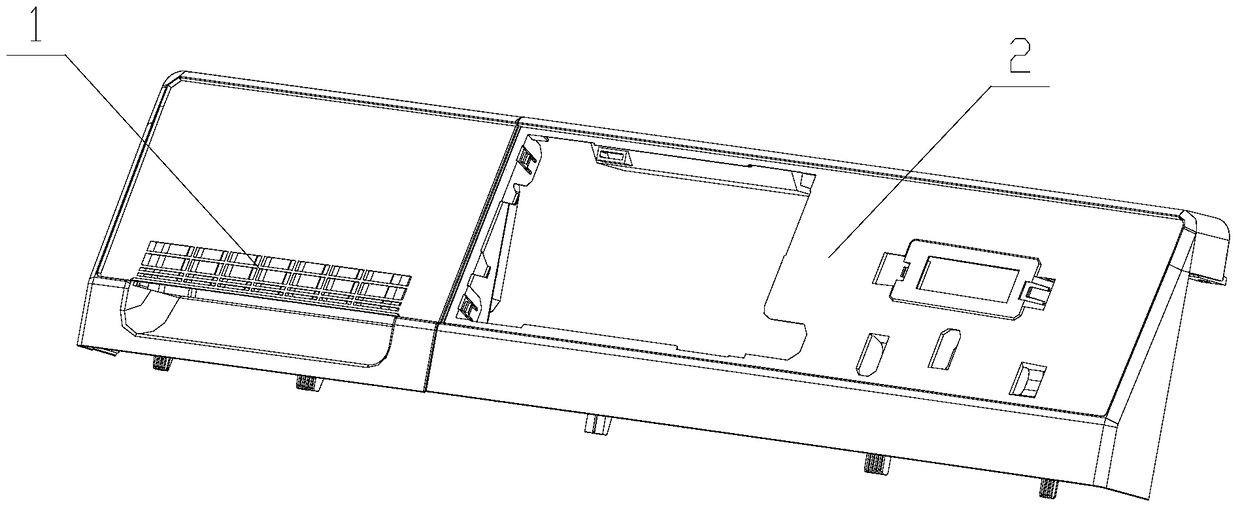
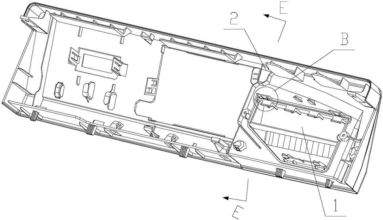
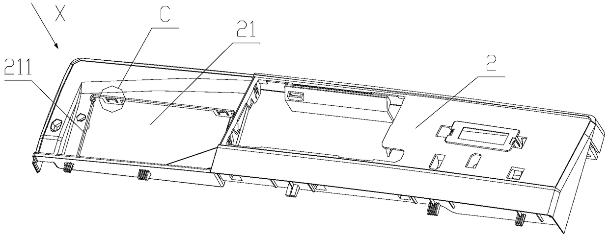
[0027] like figure 1 , figure 2 , Figure 5 and Image 6 As shown, a locking mechanism for a drum washing machine dispenser provided in Embodiment 1 includes a dispenser handle 1 and a main control board 2. The main control board 2 is provided with an assembly port 21, and the shape of the assembly port 21 is It matches the shape of the dispenser handle 1 and is used to install the dispenser handle 1. The dispenser handle 1 is plug-fitted with the main control board 2 through the assembly port 21 . The board surface of the main control board 2 is usually in the vertical direction, and the dispenser handle 1 enters and exits the main control board 2 from the direction perpendicular to the board surface of the main control board 2, which is similar to the drawer and drawer cabinet. In addition, you can also refer to the free coordinate X axis, the dispenser handle 1 is plugged and matched with the main control board 2 along the direction of the X axis.

[0028] A hook 3 is...

Embodiment 2

[0035] like Figure 9 As shown, a locking mechanism for a drum washing machine dispenser provided in Embodiment 2 includes a dispenser handle 1 and a main control board 2 . The difference between embodiment two and embodiment one is:

[0036] The fixed end of the elastic cantilever 31 is connected to the first end of the inverted U-shaped elastic piece 6, and the second end of the inverted U-shaped elastic piece 6 is fixed at the inner edge of the side wall of the assembly port 21 where the end of the guide wall 211 is located. This structure The elastic cantilever 31 and the inverted U-shaped shrapnel 6 improve the elasticity of the hook 3 and the buffering force during the locking process.


PUM


Abstract

The invention discloses a locking mechanism for a roller washing machine distributor, and belongs to the field of washing machines. The locking mechanism comprises a distributor handle and a main control board, wherein the main control board is provided with an assembling hole for mounting the distributor handle; the distributor handle is in splicing fit with the main control board through the assembling hole; a clamping hook is arranged inside the main control board; the distributor handle is provided with an inverted buckle; the clamping hook is clamped with the inverted buckle; the clamping hook comprises an elastic cantilever and a clamping table; the clamping table is fixed at the free end of the cantilever; the fixed end of the elastic cantilever is fixed on the inner edge of the side wall of the assembling hole. The locking mechanism provided by the invention can be clamped stably, the distributor handle is simple and attractive in appearance, and the visual feel of a user is good.

Description

technical field [0001] The invention relates to the field of washing machines, in particular to a locking mechanism for a dispenser of a drum washing machine. Background technique [0002] At present, most of the drum washing machines are equipped with a distributor and a main control board. The distributor usually includes structures such as a main washing box, a softener box, and a pre-washing box for holding different types of detergents. The main control board is usually provided with a plurality of operation buttons, which is convenient for users to operate the washing machine. The main control board is provided with a distributor installation hole, and the distributor is plugged and matched with the main control board through the distributor installation hole, and its movement process is similar to the push and pull of a drawer. When the dispenser is fully inserted into the dispenser installation hole, a locking mechanism is required to lock it, so as to prevent the d...

Claims


Application Information

Patent Timeline
Patent Type & Authority Patents(China)
IPC IPC(8): D06F39/02
Inventor 翁宗元刘凯张志强
Owner QINGDAO HAIER DRUM WASHING MACHINE
Why Eureka
Try Eureka