
Hydraulic system for realizing sanitation truck sweeper brush/suction nozzle floating

A hydraulic system and sweeping technology, applied in fluid pressure actuating devices, road cleaning, servo motors, etc., can solve problems such as frequent replacement, prolong the service life, reduce the number of sweeping adjustments, and ensure durability.

Active Publication Date: 2015-07-15
FUJIAN LONGMA ENVIRONMENTAL SANITATION EQUIP
View PDF5 Cites 13 Cited by
  • Summary
  • Abstract
  • Description
  • Claims
  • Application Information

AI Technical Summary

Problems solved by technology

[0004] The purpose of the present invention is to provide a hydraulic system that realizes the floating of the sweeper / suction nozzle of the sanitation vehicle, so that the floating effect of the sweeper / suction nozzle of the sanitation vehicle is good, and solves the rapid wear and tear of related parts such as the sweeper brush and the nozzle roller of the sanitation vehicle The problem of frequent replacement

Method used


Image

  • Hydraulic system for realizing sanitation truck sweeper brush/suction nozzle floating

Examples


Embodiment Construction

[0012] The hydraulic system for realizing the cleaning of the sanitation vehicle / floating suction nozzle of the present invention will be further described in detail below in conjunction with the drawings and specific embodiments.

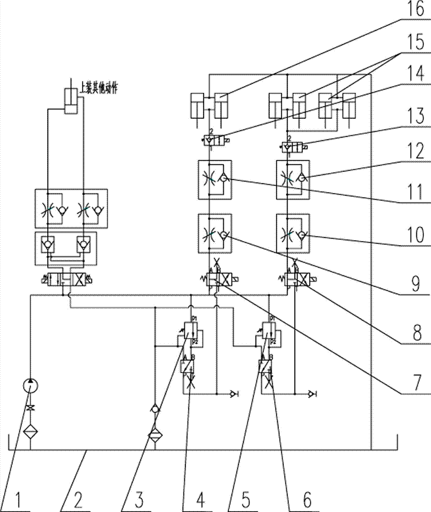
[0013] (1) As shown in the figure, the hydraulic system for sanitation vehicle sweeping / suction nozzle floating in the present invention includes a hydraulic gear pump 1, a hydraulic oil tank 2, a superimposed pressure reducing valve I3, a PB valve plate I4, and a superimposed pressure reducing valve II5 , PB valve plate II6, two-position four-way valve I7, two-position four-way valve II8, superimposed one-way throttle valve I9, superimposed one-way throttle valve II10, one-way throttle valve I11, one-way throttle valve Ⅱ12, 2-position 2-way valve Ⅱ13, 2-position 2-way valve Ⅰ14, sweeping cylinder 15 and suction nozzle cylinder 16; the oil outlet of hydraulic gear pump 1 passes through the hydraulic pipeline and the p1 port and 2nd port of superimpo...


PUM


Abstract

The invention discloses a hydraulic system for realizing sanitation truck sweeper brush / suction nozzle floating. The hydraulic system comprises a hydraulic gear pump, a stacked pressure reducing valve, a PB valve plate, a two-position four-way reversing valve, a stacked unidirectional throttle valve, a unidirectional throttle valve, a two-position two-way valve, a sweeper brush oil cylinder, a suction nozzle oil cylinder and a hydraulic oil tank, wherein an oil outlet of the pump is respectively connected with a p1 port of the stacked pressure reducing valve and a P port of the two-position four-way valve; a B port of the PB valve plate is connected with a p2 port of the stacked pressure reducing valve; a P port of the PB valve plate is connected with a T port of the two-position four-way valve; an A port of the PB valve plate and an oil discharge port of the stacked pressure reducing valve are connected with an oil return box; an A port of the two-position four-way valve is connected with the stacked unidirectional throttle valve; the other oil port of the stacked unidirectional throttle valve is connected with the unidirectional throttle valve; the other oil port of the unidirectional throttle valve is connected with one port of the two-position two-way valve; the other port of the two-position two-way valve is connected with a rod cavity of the sweeper brush oil cylinder / the suction nozzle oil cylinder; a rod-free cavity of the sweeper brush oil cylinder / the suction nozzle oil cylinder is connected with the hydraulic oil tank. The hydraulic system enables the sanitation truck sweeper brush / suction nozzle floating effect to be good, and sweeper brush and suction nozzle rolling wheels are prevented from being abraded quickly.

Description

technical field [0001] The invention relates to road sanitation vehicle equipment, in particular to a hydraulic system for realizing the cleaning of the sanitation vehicle and the floating of the suction nozzle. Background technique [0002] At present, urban road cleaning operations have basically realized the mechanized operation mode, which is completed by special vehicles for road cleaning operations. The sweeping plate / suction nozzle of the existing road cleaning vehicles generally adopts the cylinder or the oil cylinder to perform the lifting action, which has the following defects: [0003] When the existing sweeper performs cleaning operations, the rubber wheel of the suction nozzle is in contact with the ground almost under the condition of bearing all the weight of the suction nozzle, so that the relevant parts such as the suction nozzle roller wear quickly and need to be replaced frequently. In order to change this situation, a The spring pulls the suction nozzle...

Claims


Application Information

Patent Timeline
IPC IPC(8): F15B11/16E01H1/05E01H1/08
CPCE01H1/05E01H1/08E01H1/0827E01H2001/0881F15B11/16F15B13/06
Inventor 杨锦华李春邓钦坤
Owner FUJIAN LONGMA ENVIRONMENTAL SANITATION EQUIP
Learn More