Multi-manifold valve seat

A valve seat and valve installation technology, which is used in multi-port valves, valve devices, fluid pressure actuation devices, etc., can solve the problems of difficult quality control, easy fluctuations in processing quality, and large installation space occupied by the pilot valve seat. Achieve the effect of solving the limited number of CNC tool positions, solving the high requirements for product sealing, and reducing the difficulty of processing technology

Active Publication Date: 2017-03-22
JINAN FUCHI TECH CO LTD
View PDF8 Cites 0 Cited by
  • Summary
  • Abstract
  • Description
  • Claims
  • Application Information

AI Technical Summary

Problems solved by technology

[0002] Pneumatic equipment in the prior art widely uses the pilot valve structure. There are many problems in the prior art pilot valve structure. For example, multiple pilot valves need to be used in the same equipment or system at the same time. Pilot valve seat, so multiple pilot valve seats occupy a large installation space, the structure is heavy, and not compact. At the same time, due to the large number of parts to be processed, the sealing and matching surfaces between parts are processed with high precision, the process is complicated, and the quality is not easy. control, the processing quality is prone to fluctuations, and the production efficiency is low

Method used


Image

  • Multi-manifold valve seat
  • Multi-manifold valve seat
  • Multi-manifold valve seat

Examples


Embodiment Construction

[0020] In order to better understand the present invention, the implementation manner of the present invention will be explained in detail below in conjunction with the accompanying drawings.

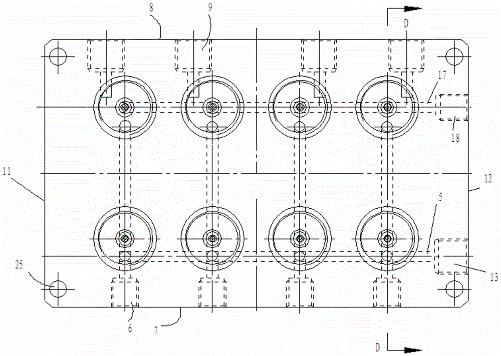
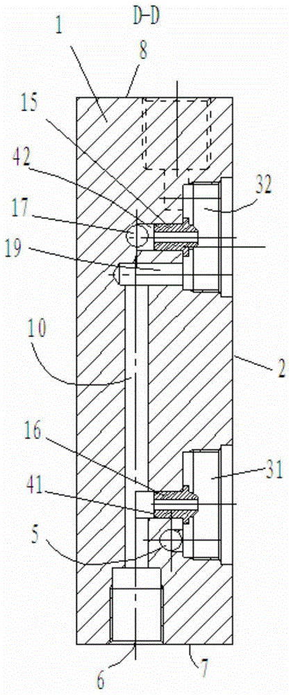
[0021] Such as Figure 1 to Figure 6 As shown, a multi-unit valve seat includes a valve seat body 1. The valve seat body 1 is provided with a plurality of air grooves 1 31 and 2 32 on the end face 2 connected to the valve cover. 31. The bottom of the air tank 2 32 is respectively provided with a valve nozzle installation hole 1 41 and a valve nozzle installation hole 2 42 which are vertically arranged. Mouth one 16, valve mouth two 15, be provided with the air inlet channel one 5 that is connected with air groove one 31 at valve mouth mounting hole 41 one sides, air inlet channel one 5 is connected with input port one 13, input port one 13 is located at The right end face 12 bottom of valve seat body, the right end face 12 upper part of valve seat body is provided with air inlet passag...


PUM


Abstract

The invention discloses a multi-connected integrated assembling valve seat. The multi-connected integrated assembling valve seat comprises a valve seat body, wherein multiple air grooves I, multiple air grooves II, multiple valve nozzle installation holes I and multiple valve nozzle installation holes II are formed in the valve seat body; valve nozzles I and valve nozzles II are arranged in the valve nozzle installation holes I and the valve nozzle installation holes II; one side of each valve nozzle installation hole I is provided with an air inlet passage I which is connected with the corresponding air groove I; the air inlet passages I are connected with input openings I; the valve seat body is provided with an air inlet passage II and an air inlet passage III; the air inlet passage II is connected with an air passage I; an air output opening I of the air passage I is formed in the front end surface of the valve seat body; an air output opening II is formed in the valve seat body; the valve nozzle installation holes I are connected with the air passage I; the air inlet passage III is connected with an input opening II; the air inlet passage III is connected with the air grooves II. According to the multi-connected integrated assembling valve seat disclosed by the invention, by changing a pilot valve seat which is in dispersed installation into an integrated installation structure, the assembling number and the installation space of parts are reduced, the difficulty of a machining technology is reduced, the problems of an existing pilot valve seat that the occupied space is large and the whole weight is heavy are solved, and the multi-connected integrated assembling valve seat is particularly suitable for scale production.

Description

technical field [0001] The invention relates to the technical field of pneumatic equipment, in particular to a multi-connected manifold valve seat. Background technique [0002] Pneumatic equipment in the prior art widely uses the pilot valve structure. There are many problems in the prior art pilot valve structure. For example, multiple pilot valves need to be used in the same equipment or system at the same time. Pilot valve seat, so multiple pilot valve seats occupy a large installation space, the structure is heavy, and not compact. At the same time, due to the large number of parts to be processed, the sealing and matching surfaces between parts are processed with high precision, the process is complicated, and the quality is not easy. control, the processing quality is prone to fluctuations, and the production efficiency is low. Contents of the invention [0003] The purpose of the present invention is to provide a multi-connected manifold valve seat to solve the ab...

Claims


Application Information

Patent Timeline
Patent Type & Authority Patents(China)
IPC IPC(8): F15B13/02F16K11/00
CPCF15B13/02F16K11/00
Inventor 张峰
Owner JINAN FUCHI TECH CO LTD
Why Eureka
Try Eureka