Bidirectional simultaneous rotary blade bundle for mixer

a rotary blade and mixer technology, applied in the field of mixers, can solve the problems of increasing the production cost of a product, affecting the efficiency of the mixer, and the eccentric installation of the driven gear, so as to prevent the occurrence of eccentricity during the rotation, reduce the steps of the reverse direction power transmission, and reduce the production cos

Pending Publication Date: 2022-02-10
CUCKOO ELECTRONICS CO LTD
View PDF0 Cites 1 Cited by
  • Summary
  • Abstract
  • Description
  • Claims
  • Application Information

AI Technical Summary

Benefits of technology

[0018]The bidirectional simultaneous rotary blade bundle for the mixer of the present disclosure including the aforementioned configuration has the following effects.
[0019]First, in the present disclosure, since inner gear teeth having a belt shape are formed at an inner circumferential surface of a reverse rotor and a plurality of horizontal insertion gears is provided between the inner gear teeth and a central gear and engaged with both the inner gear teeth and the central gear, there is an advantage in that an occurrence of eccentricity during a rotation is prevented so that a noise does not occur.
[0020]Second, in the present disclosure, between the inner gear teeth of the reverse rotor and the central gear, the plurality of horizontal insertion gears is engaged with both the inner gear teeth and the central gear and arranged at equal intervals, and the horizontal insertion gears rotate the inner gear teeth in the same direction of a rotating direction of the horizontal insertion gears, so that there is an advantage in that a rotating balance of the reverse rotor and a forward shaft is automatically maintained, thereby having an advantage of a rotation with stable and reliable.
[0021]Third, in the present disclosure, between the central gear and the inner gear teeth of the reverse rotor, only horizontal insertion gear that is one power transmission member is adopted, so that there is an advantage in that steps of a reverse direction power transmission are minimized, thereby having an advantage of reducing both the number of parts and an assembly time of a product, resulting in an advantage of reducing a production cost of the product.
[0022]Fourth, in the present disclosure, by realizing the reverse direction rotation only with the horizontal insertion gear without adopting the large number of gears that occupy a large volume in both horizontal and vertical directions, there are advantages in that a volume of the blade bundle is capable of being reduced and the mixer is capable of being miniaturized.

Problems solved by technology

First, the technology of Korean Patent No. 10-1862587 adopted a plurality of driven gears so as to transfer a rotational force of a driving gear to a reverse rotation gear that is fastened to a reverse direction rotor, but the driven gears were inevitably eccentrically installed from the rotary shaft.
In the installation structure of the driven gear, since a power transmission process of the reverse direction was eccentric, overall rotation was inevitably eccentric to one side.
As a result, problems may occur in rotational efficiency, rotational stability, and rotational reliability, and also there may be a problem of causing noise.
As described above, since the number of parts was increased due to the large number of gears that occupy a large volume in both horizontal and vertical directions and an assembly time was also increased, there was a problem in that a production cost of a product was increased, and also there was a problem of miniaturizing the product due to a problem of a large volume of a blade bundle.

Method used


Image

  • Bidirectional simultaneous rotary blade bundle for mixer
  • Bidirectional simultaneous rotary blade bundle for mixer
  • Bidirectional simultaneous rotary blade bundle for mixer

Examples


Embodiment Construction

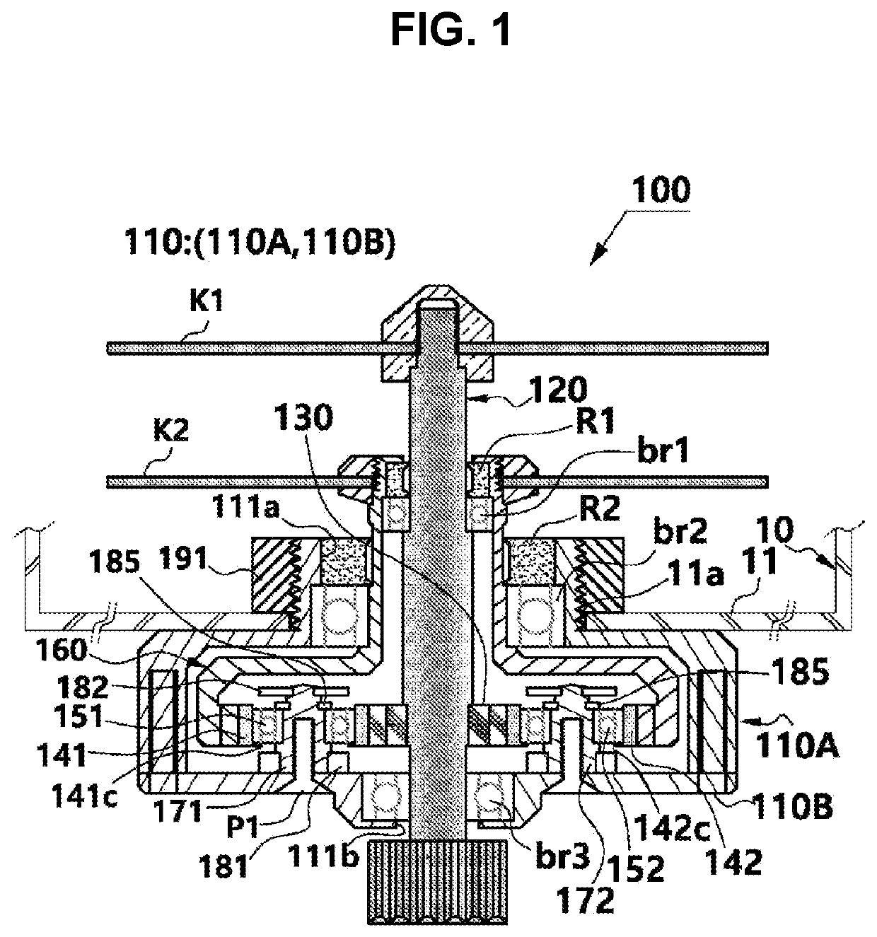
[0033]Hereinafter, a bidirectional simultaneous rotary blade bundle for a mixer according to a preferred embodiment of the present disclosure will be described in detail with reference to accompanying drawings.

[0034]The present disclosure relates to a mixer that may include: a container 10 having a cylindrical shape for containing foods including fruits, meats, vegetables, coffee, and grains; a motor housing (not illustrated) coupled to the container 10 at a position below the container 10; a motor (not illustrated) embedded in the motor housing (not illustrated) and configured to be rotatable at a position inside the motor housing; and a blade bundle 100 configured to be rotated according to a rotation of the motor by receiving a rotational force of the motor and configured to cut, grind, or mill the foods existing in the container 10. Particularly, the present disclosure relates to the blade bundle 100 that is a key component of the mixer.

[0035]The container 10, the motor housing,...


PUM


Abstract

Provided is a bidirectional simultaneous rotary blade bundle for a mixer, the bidirectional simultaneous rotary blade bundle comprising: a housing (110); a forward rotary shaft (120) installed on the housing (110); a forward rotation blade (K1) provided on the forward rotary shaft (120); a central gear (130) axially installed on the forward rotary shaft (120); horizontal insertion gears (141,142, and 143) engaged with the central gear (130); a reverse rotor (160), of which inner gear teeth (164) are engaged with and rotate on the outside of the horizontal insertion gears (141, 142, and 143); and a reverse rotation blade (K2) installed on the reverse rotor (160), wherein the horizontal insertion gears (141, 142, and 143) are rotated in the reverse direction according to the forward rotation of the central gear (130) such that the inner gear teeth (164) are rotated in the reverse direction.

Description

TECHNICAL FIELD[0001]The present disclosure relates to a mixer.BACKGROUND ART[0002]Generally, a mixer is an electric machine for processing foods such as fruits, vegetables, grains, etc. by mincing, juicing, mixing, cutting (chopping), or grinding (hereinafter, referred to as “grind” for a convenience of explanation) so that the foods in various forms can be ingested.[0003]Fundamentally, a mixer may include a motor housing in which a motor is installed, a container coupled to the motor housing and provided with a rotary blade that receives a rotational force of the motor, and a lid that opens and closes an upper end of the container.[0004]The rotary blade constructed inside the container may be provided by being mounted on a rotary shaft of a blade bundle.[0005]As the related art with respect to such a rotary blade, “A two way rotatable knife assembly for a mixer” that is Korean Patent No. 10-1862587 (published on May 31, 2018) filed and registered as a patent in Korea by the presen...

Claims


Application Information

Patent Timeline
Patent Type & Authority Applications(United States)
IPC IPC(8): A47J43/07A47J43/08
CPCA47J43/0722A47J43/085B01F27/84B01F27/808B01F35/33B26D1/28B26D5/086B26D7/2614
Inventor KIM, YOUNGJIN
Owner CUCKOO ELECTRONICS CO LTD
Why Eureka
Try Eureka