
Tunnel health detection apparatus without affecting tunnel operation

A technology for health detection and tunneling, which is applied to measurement devices, optical devices, optical testing flaws/defects, etc., can solve the problems of easy water accumulation on the track, potential safety hazards, and high costs, and achieve the effect of reducing potential safety hazards.

Inactive Publication Date: 2015-07-15
SICHUAN JINMA TECH
View PDF7 Cites 9 Cited by
  • Summary
  • Abstract
  • Description
  • Claims
  • Application Information

AI Technical Summary

Problems solved by technology

[0004] (1) At the present stage, the health inspection of most tunnels adopts manual detection method, which requires engineering inspection personnel to place the detector at a designated location for detection, which is extremely low in work efficiency, and for large tunnels, the manual detection method is too heavy. high labor cost
In addition, the manual inspection method requires engineering inspectors to work in the tunnel, which has great potential safety hazards
[0005] (2) In order to improve the detection efficiency and reduce the detection cost, some tunnel health intelligent detection equipment has appeared on the market. However, the traditional tunnel health intelligent detection equipment adopts the method of installing detectors on the tunnel road surface, and the detection work must be stopped in the tunnel. It can only be carried out at a certain time, which affects the normal operation of the tunnel
In order not to affect the normal operation of the tunnel, some tunnel health detection devices adopt the method of digging the track on the tunnel road surface. Although this detection method can reduce the impact on the tunnel operation, the cost is high, and the excavated track is prone to water accumulation. adverse effect on the detector

Method used


Image

  • Tunnel health detection apparatus without affecting tunnel operation
  • Tunnel health detection apparatus without affecting tunnel operation
  • Tunnel health detection apparatus without affecting tunnel operation

Examples


Embodiment Construction

[0023] The technical solution of the present invention will be further described in detail below in conjunction with the accompanying drawings, but the protection scope of the present invention is not limited to the following description.

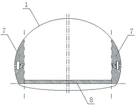
[0024] The tunnel health detection device that does not affect the operation of the tunnel, including a detector, the detector is installed on the tunnel arch wall 1, without installing any detection device on the tunnel road surface, and the detection operation will not have any impact on the normal operation of the tunnel .

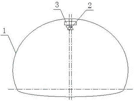
[0025] [Example 1] such as figure 1 As shown, the detector is a high-speed camera 2, and the high-speed camera 2 is installed on the tunnel arch wall 1 through the first bearing track 3, and the high-speed camera 2 slides on the first bearing track 3 to take tunnel images to analyze tunnel surface cracks, It can realize tunnel crack detection without blind zone.

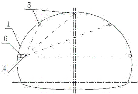
[0026] [Example 2] such as figure 2 As shown, the...


PUM


Abstract

The invention discloses a tunnel health detection apparatus without affecting tunnel operation. The apparatus comprises a detector, and the detector is arranged on a tunnel arch buttress (1). The detector is arranged on the tunnel arch buttress, so detection work enforcement has no influences on the normal operation of a tunnel. A high speed camera walks on a bearing track and shoots the photograph of the tunnel arch buttress, and image analysis is carried out to realize non-blind area tunnel crack detection. A range finder is arranged on the bearing track, the tunnel arch buttress is provided with a target bar paralleling to the bearing track in the radial direction and attached to the surface of the tunnel arch buttress, the range finder walks on the bearing track to detect a distance from the target bar to the range finder in real time, and distance transformation analysis is carried out to realize non-blind area tunnel deformation detection. The detector is arranged on the arch buttress of the side edge area at two sides of the tunnel, so in the detection process, even the detector carelessly falls, the detector does not fall to the pavement, and does not affect the normal operation of the tunnel, thereby the hidden safety trouble is reduced.

Description

technical field [0001] The invention relates to a tunnel health detection device which does not affect tunnel operation. Background technique [0002] With the increasing number of highways, railways, and urban rail transit projects, more and more tunnel projects are used, and tunnels have high engineering requirements during construction, especially in terms of construction technology, support requirements and deformation. . Tunnel crack and deformation monitoring and control are very important contents in the tunnel construction process and subsequent tunnel maintenance process. How to accurately detect tunnel cracks and deformation is a hot and difficult point that engineers have always been concerned about. [0003] Traditional tunnel health detection devices have the following defects: [0004] (1) At the present stage, the health inspection of most tunnels adopts manual detection method, which requires engineering inspection personnel to place the detector at a desig...

Claims


Application Information

Patent Timeline
IPC IPC(8): G01N21/88G01B11/16
Inventor 杨绍荃杨波
Owner SICHUAN JINMA TECH
Learn More