Display device

A display device and a technology for displaying images, which can be used in static indicators, nonlinear optics, instruments, etc., and can solve problems such as reducing the quality of displayed images

Active Publication Date: 2015-07-15
TIANMA MICRO ELECTRONICS CO LTD
View PDF8 Cites 4 Cited by
  • Summary
  • Abstract
  • Description
  • Claims
  • Application Information

AI Technical Summary

Problems solved by technology

[0004] When the ideal image data (hereinafter referred to as "original image"), which is the source of the display image, is displayed on the above-mentioned display device, the position of the boundary area between the light pattern and the dark pattern of the original

Method used


Image

  • Display device
  • Display device
  • Display device

Examples


Embodiment 1

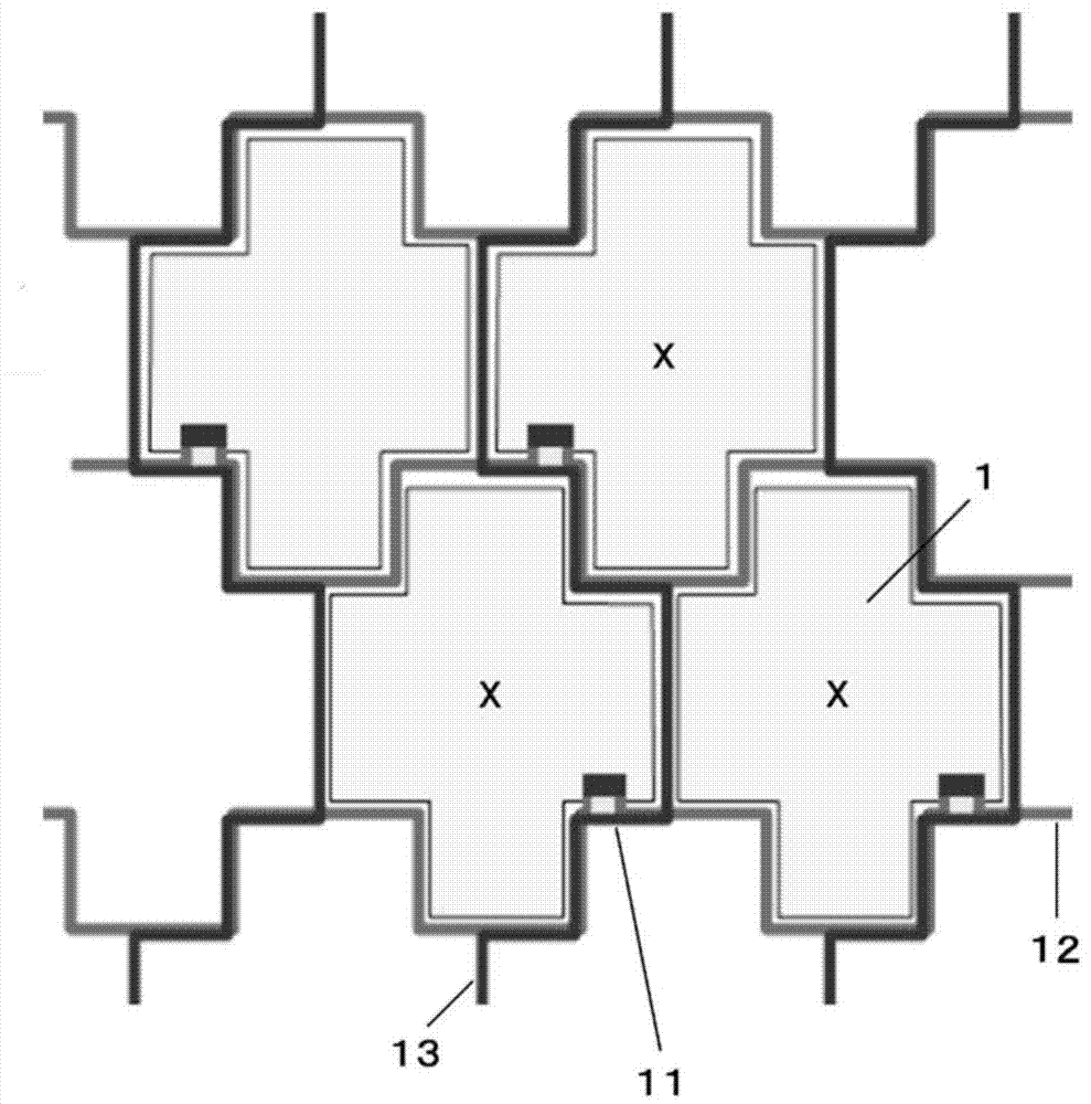
[0059] refer to figure 1 The structure of the liquid crystal display device in Example 1 of the present invention will be described.

[0060] In the case of a liquid crystal display device, a prescribed voltage is applied to each pixel 1 to drive the liquid crystal, whereby the transmittance of each pixel 1 is controlled. Light emitted from the backlight transmits through each pixel 1 and is emitted from the display surface, so the transmittance of each pixel 1 is controlled, so that the brightness of each pixel can be controlled to display an image.

[0061] A switching element 11 is provided on each pixel 1 to apply a prescribed voltage to each pixel 1 , and a signal voltage of a data wiring is applied through the switching element 11 . Also, the switching element 11 is provided with a gate electrode connected to the gate wiring 12 so as to control the switching element, and ON / OFF of the switching element can be controlled by switching the gate voltage.

[0062] Usually,...

Embodiment 2

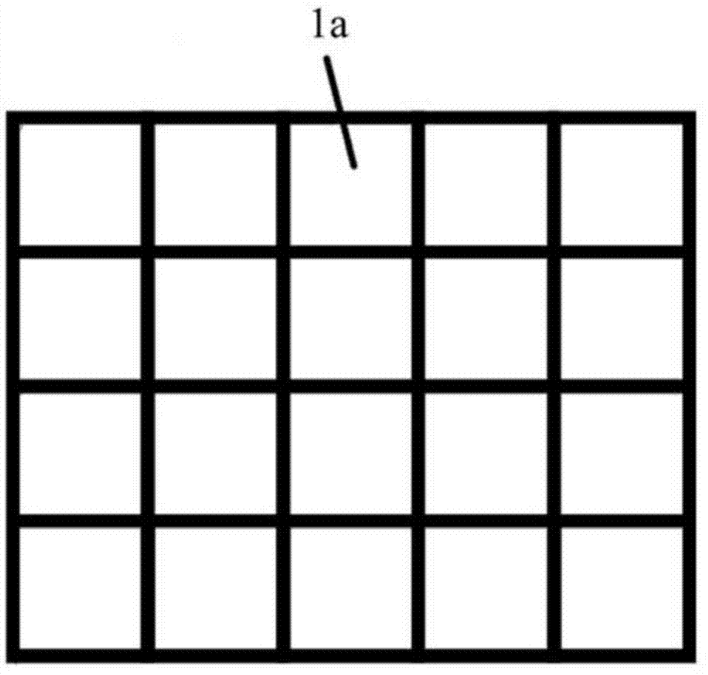
[0079] In Example 2 as another embodiment of the present invention, as Figure 7 As shown, like Embodiment 1, the shape of the pixel 2 is cross-shaped, and the pixels are rotated and arranged obliquely so that the array of the centers of gravity of the pixels is changed. As indicated by reference numeral 3a, the pixel array is a square array. In other words, the pixels constitute an array in which the pixels are arranged point-symmetrically in the horizontal row direction and the vertical row direction. Also, the boundaries of these pixels are not straight lines in any direction.

[0080] That is, the centers of gravity of the pixels 2 are arranged in a square array in which horizontal rows and vertical rows of pixels are linearly arranged, thereby providing an advantage that the conversion process from the original image to the displayed image can be compared with the triangular array. Relatively easy to do.

Embodiment 3

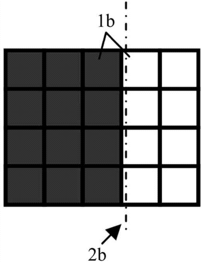
[0082] In embodiment 3 of the present invention, as Figure 8 As shown, there is provided an array in which, while setting the pixel shape to the same pixel shape as in Embodiment 1, substitution occurs in the horizontal row and vertical direction in the pixel array. As indicated by reference numeral 3b, the pixel array has a difference of 90 degrees compared with the ordinary triangular array. In other words, the pixels constitute an array in which the pixels are arranged line-symmetrically in the vertical row direction and point-symmetrically in the obliquely upward and obliquely downward directions. Also, the boundaries of these pixels are not straight lines in any direction.

[0083] That is to say, in Embodiment 1, the centers of gravity of the pixels 1 are arranged linearly in the horizontal direction, and in the direction of the vertical rows, the centers of gravity of the pixels are arranged in a zigzag manner, wherein the positions of the centers of gravity of each p...


PUM


Abstract

A display device which can relax a discontinuity feeling in displaying is provided. The display device according to the present invention operated by using a display method in which a lot of pixels having aperture parts are arranged and in which the respective pixels are controlled in a brightness to display images comprises such a pixel structure and a pixel array that concave parts are formed in different four directions and the other directions which are lateral directions on the same plane of the aperture parts of the pixels described above and that the aperture parts of the adjacent pixels are arranged to the concave parts described above.

Description

technical field [0001] The present invention relates to a structure of a display device applied to an overall flat panel display, in particular to the opening shape of a display pixel (hereinafter referred to as "pixel") in the display device. The "pixel" mentioned above refers to the opening area (hereinafter referred to as "opening"). Unless otherwise specified, the brightness of the pixel can actually be controlled, and the light-shielding area between the pixels is not included. Background technique [0002] As a mainstream display device for displaying pictures and images, flat panel displays have various display methods, such as LCD (Liquid Crystal Display), PDP (Plasma Display) and OLED (Organic Electroluminescence Flat Panel Display), which adopt many Small pixels and the display method of controlling the brightness of each pixel to display an image, so the present invention can be applied to these display methods. [0003] To cite LCD as a representative flat panel...

Claims


Application Information

Patent Timeline
IPC IPC(8): G02F1/1333
CPCG09G2300/08G09G2340/0457G09G3/2007G09G2300/0439G09G2300/0426
Inventor 佐佐木健
Owner TIANMA MICRO ELECTRONICS CO LTD
Why Eureka
Try Eureka