
Chip package structure

A chip packaging structure and chip technology, applied in static memory, instruments, electrical components, etc., can solve the problems of increased production cost, multiple spaces, occupation, etc., and achieve the effect of low manufacturing cost and short signal transmission path

Active Publication Date: 2017-11-14
NAN YA TECH
View PDF4 Cites 0 Cited by
  • Summary
  • Abstract
  • Description
  • Claims
  • Application Information

AI Technical Summary

Problems solved by technology

These wires need additional process to form, so it will increase the production cost
In addition, long wires cause signal delay and take up more space, resulting in a large stack of memory chips

Method used


Image

  • Chip package structure
  • Chip package structure
  • Chip package structure

Examples


Embodiment Construction

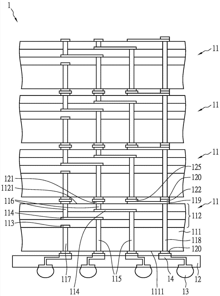
[0052] Figure 1A It is a schematic diagram of a chip package structure 1 according to an embodiment of the present invention. Such as Figure 1A As shown, the chip package structure 1 includes at least one chip 11 . In this embodiment, the chip packaging structure 1 includes a plurality of chips 11 . A plurality of chips 11 are stacked on a circuit board 12 , wherein at least a plurality of welding bumps 13 are fixed on the bottom surface of the circuit board 12 . The plurality of welding bumps 13 correspond to the chip 11 of the chip package 1 . The chip package 1 is electrically connected to the pads 14 on the upper surface of the circuit board 12 , and the plurality of pads 14 are connected to the corresponding bumps 13 . When a signal is applied to a bump 13, a corresponding chip 11 can be activated.

[0053] The chip 11 can be a memory chip, such as a dynamic access memory chip (DRAM chip) or a flash memory chip (flash memory chip). Essentially, a memory chip may con...


PUM


Abstract

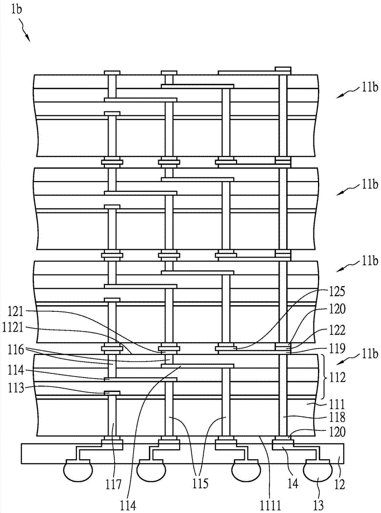
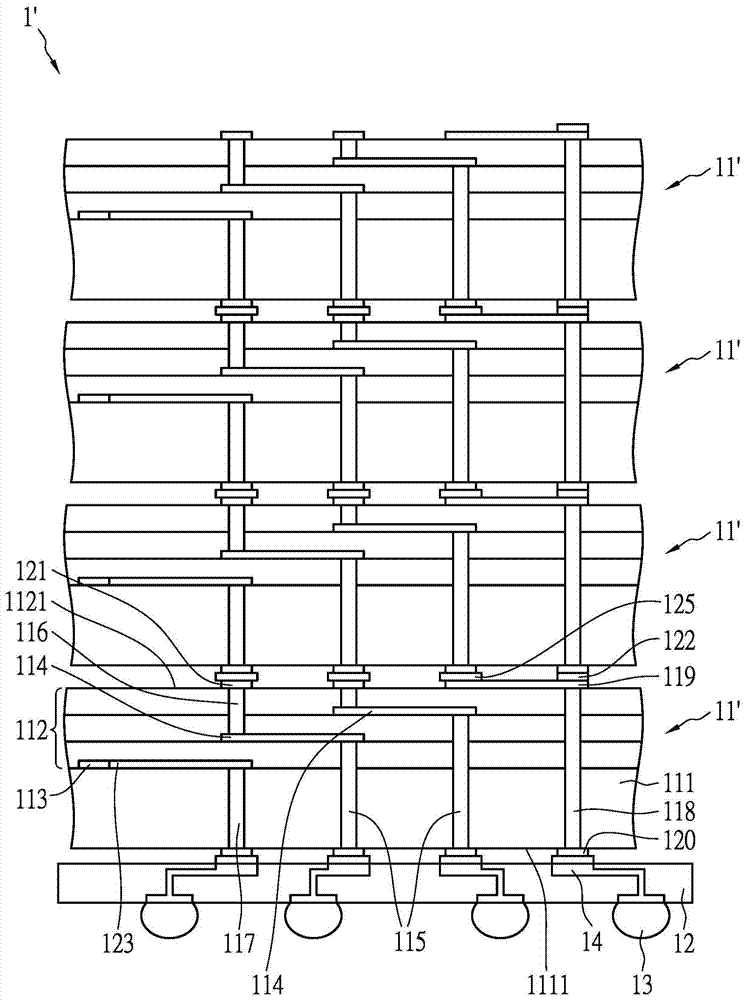
A chip packaging structure includes a chip. A plurality of first pads and a plurality of second pads are arranged on two sides of the chip respectively. The plurality of first pads are electrically connected to a chip select electrode, the plurality of second pads and the exposed conductor correspondingly. The first pads and the second pads electrically connected to each other are not aligned in the vertical direction, and are connected by vertical connectors and inner conductors. The chip includes a plurality of insulating layers, and the inner conductors are separated at different heights by the plurality of insulating layers.

Description

technical field [0001] The invention relates to a chip package comprising at least one stackable chip. Background technique [0002] Chip stacking technology allows two chips to be closer together, thereby enabling faster data transmission between the two chips and consuming less energy. Memory chips can be stacked together to obtain a memory module with larger storage space. In addition to stacking the same two chips, chips with different functions can also be stacked together to combine different functions. [0003] In a memory chip stack, each memory chip has a chip select (CS) terminal. The chip select electrode is used to activate the memory chip. For example, a DRAM chip may have a row address strobe (RAS), a row address strobe (column address strobe) or a chip select pin as a chip select electrode. When a signal is applied to the chip-select electrodes of a chip in the stack of memory chips, that chip can be accessed while other chips cannot. [0004] Traditional...

Claims


Application Information

Patent Timeline
Patent Type & Authority Patents(China)
IPC IPC(8): H01L23/31
CPCG11C5/063H01L23/481H01L23/5226H01L25/0657H01L2224/16145H01L2225/06513H01L2225/06517H01L2225/06527H01L2225/06565H01L23/5384H01L23/5386H01L25/074
Inventor 林柏均
Owner NAN YA TECH
Learn More