
Test system and method for testing field performance of combine harvester

A technology of combine harvester and test system, which is applied in the field of combine harvester field performance test and test system, can solve the problem that the rotational speed and torque of the crankshaft of the vibrating screen and the rotational speed of the fan are individually uncontrollable, the double longitudinal axial flow drum is not included, and the overall Control matching and other issues

Active Publication Date: 2015-07-22
JIANGSU UNIV
View PDF5 Cites 8 Cited by
  • Summary
  • Abstract
  • Description
  • Claims
  • Application Information

AI Technical Summary

Problems solved by technology

Although the patent realizes the intelligent control of the tangential flow drum, the control is too one-sided and does not include the control of the double longitudinal axial flow drum, vibrating screen and fan, which also have a great influence on the cleaning rate, so that the control effect is too limited. Inability to achieve overall control matching effect
[0005] In summary, the controllability of each component in the threshing system of the combine harvester in the prior art is relatively low, mainly in the aspect of monitoring and research. During the actual field operation stage, the rotational speed of the tangential flow drum and the double longitudinal axial flow drum in the threshing system and torque, the speed of the crank shaft of the vibrating screen and the fan are not controllable independently

Method used


Image

  • Test system and method for testing field performance of combine harvester

Examples


Embodiment Construction

[0020] The technical solution of the present invention will be described in further detail below in conjunction with the accompanying drawings and specific embodiments.

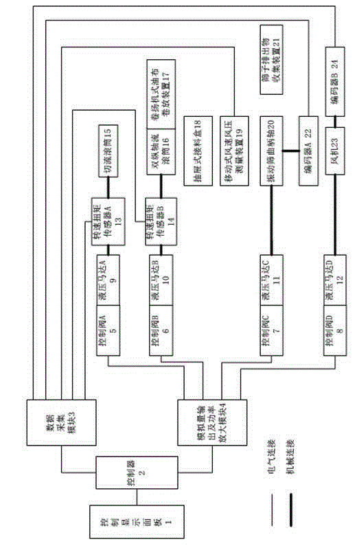
[0021] The field performance test system of the combine harvester of the present invention comprises a header, a conveying device, a threshing system, a granary, an engine, a traveling device, a transmission system, and a manipulation control device. Such as figure 1 As shown, the cutting flow drum 15, the double longitudinal axial flow drum 16, the vibrating screen crank shaft 20 and the fan 23 in the threshing system are respectively powered by the hydraulic motor A9, the hydraulic motor B10, the hydraulic motor C11 and the hydraulic motor D12, and the hydraulic motor A9 , hydraulic motor B10, hydraulic motor C11, and hydraulic motor D12 are respectively connected to control valve A5, control valve B6, control valve C7, and control valve D8, and control valve A5, control valve B6, control valve C7, and con...


PUM


Abstract

The invention discloses a test system and method for testing the field performance of a combine harvester and belongs to testing devices for combine harvesters. The test system is composed of a header, a conveying device, a flow cutting roller, two longitudinal axial flow rollers, a vibrating screen, a draught fan, a traveling device, an engine, a transmission system, a hydraulic system, an electrical system and the like. Power is supplied to the flow cutting roller, the two longitudinal axial flow rollers, the vibrating screen and the draught fan by hydraulic motors which are independent of one another respectively, corresponding sensors are installed on the flow cutting roller, the two longitudinal axial flow rollers, the vibrating screen and the draught fan to monitor the rotating speeds and the torques of the flow cutting roller, the two longitudinal axial flow rollers, the vibrating screen and the draught fan respectively, and stable work can be achieved during actual field operation. The test system and method mainly aims to solve the problems that the rotating speeds and torques of a flow cutting roller and two longitudinal axial flow rollers in a combine harvester threshing system can not be controlled independently, and the rotating speeds of a vibrating screen and a draught fan can not be controlled independently either. The speeds of the four parts are controlled independently, observation is conducted by means of the rotating speed and torque sensors or an encoder, and in this way, the cleaning losses and the non-threshing rate of grains under different rotating speed conditions can be measured. The system and method are applied to operation of field harvesters.

Description

technical field [0001] The invention relates to a field performance test system and a test method of a combine harvester, belonging to the field of rice field harvesting facilities. Background technique [0002] With the rapid development of agricultural equipment, the application scale, harvesting performance and automation degree of combine harvesters have become important indicators of modern agriculture. At present, the existing combine harvesters are not perfect in structure and function, and the cleaning quality of the harvesters is low when the harvesters are actually operating in the field. The main reason for this problem is that the structural design of the threshing system of the combine harvester is not perfect, and the tangential flow drum, double longitudinal axial flow drum, vibrating screen crankshaft and fan are driven by the same power, which cannot be controlled by speed regulation separately. The speed is set according to empirical parameters, so the cle...

Claims


Application Information

Patent Timeline
Patent Type & Authority Applications(China)
IPC IPC(8): A01D41/127
Inventor 魏新华宋琦尹建军李林吴姝
Owner JIANGSU UNIV
Learn More