Zipper penetrating machine

A head threading machine and zipper technology, applied in the field of zipper threading machines, can solve the problems of inability to meet customer needs, inability to realize automated assembly line operations, etc., and achieve the effect of accurate knife edge positioning

Active Publication Date: 2015-07-22
温州宏业精机有限公司
View PDF6 Cites 7 Cited by
  • Summary
  • Abstract
  • Description
  • Claims
  • Application Information

AI Technical Summary

Problems solved by technology

The existing zipper threading machine has the following technical defects: since this zipper threading machine penetrates from the tail of the slider in the process of threading the slider, that is, the tail of the slider is at the rear end when the zipper is output. , is to use the U-shaped card code machine to install th

Method used


Image

  • Zipper penetrating machine
  • Zipper penetrating machine
  • Zipper penetrating machine

Examples


Embodiment Construction

[0017] The present invention will be further described below in conjunction with accompanying drawing:

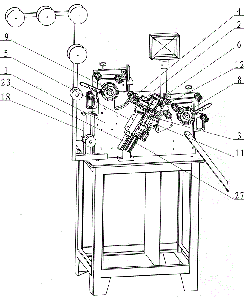
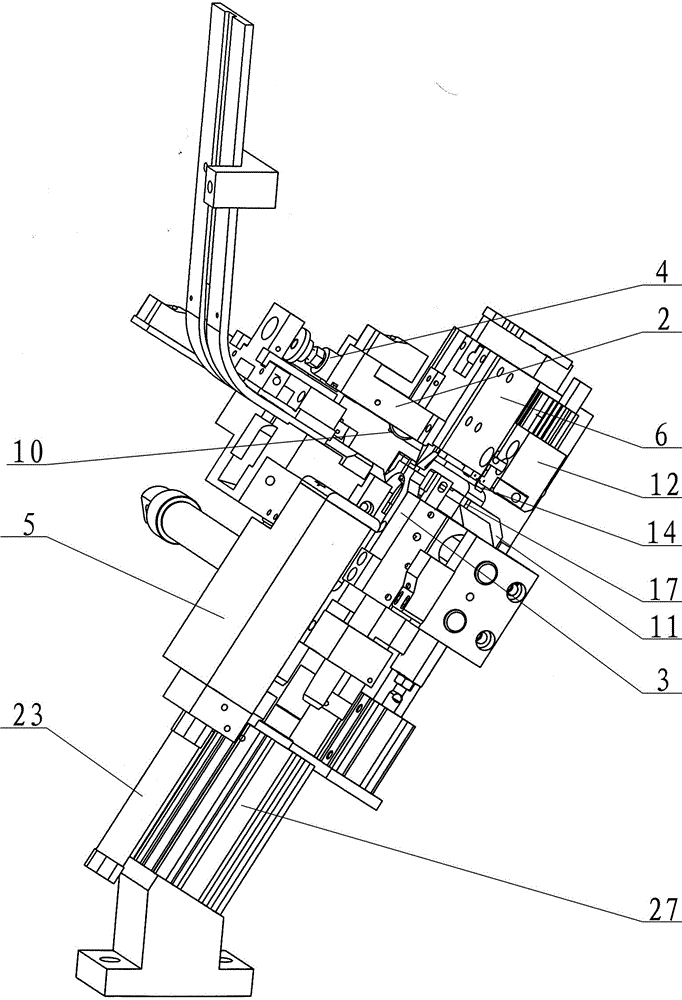
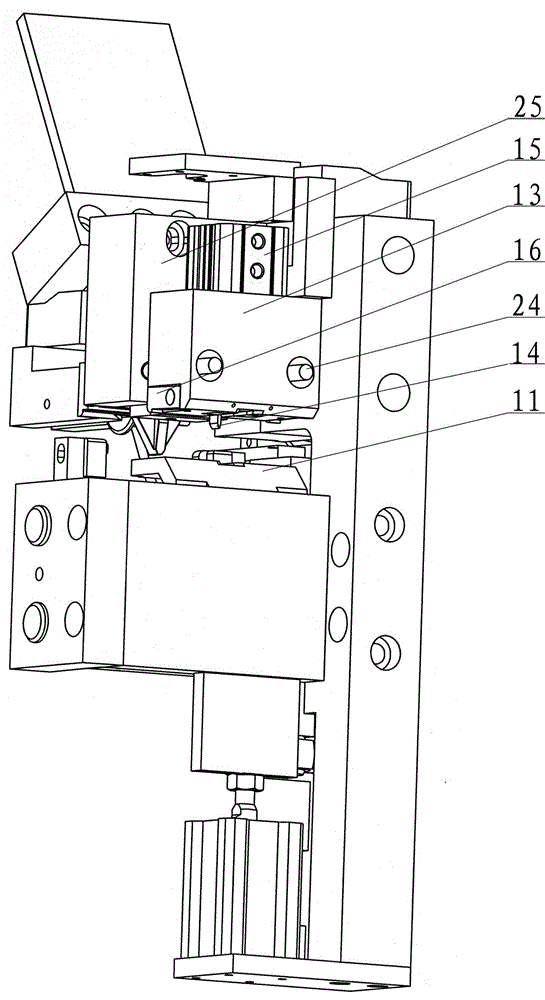
[0018] Depend on Figure 1 to Figure 5 As shown, the zipper threading machine includes a frame 1, a zipper traction mechanism, a zipper sensing detection device 2, a slider mold 3, a head feeder 4, a zipper sliding groove 5 and a belt pin positioning device 6, and a slider mold 3 There is a slider safety release mechanism 7 on the top, two zipper traction mechanisms, namely a forward traction mechanism 8 and a backward traction mechanism 9, and a roller 10 is provided in the zipper induction detection device 2, and the roller 10 is connected with the zipper that can move up and down. The slide groove 5 is corresponding; the right side of the slider mold 3 is provided with a zipper lower molding plate 11 that can slide up and down, and a slider edge positioning device 12 is provided above the zipper lower molding plate 11, and the slider edge positioning device 12 includes a...


PUM


Abstract

The invention relates to a zipper penetrating machine. The zipper penetrating machine can be mainly used for solving the problems that an existing zipper penetrating machine is not matched with a U-shaped clamping weight machine and automatic assembly line work can not be realized. The zipper penetrating machine is characterized in that two zipper drawing mechanisms are arranged, a roller (10) is arranged in a zipper induction detection device (2), a puller cutter point locating device (12) is arranged above a zipper lower mould pressure plate (11), a puller mould (3) can move along lateral direction vertical to a zipper moving direction, the puller mould (3) has two working positions, one is a position corresponding to a sender (4), and the other one is a position enabling the puller to be corresponding to the zipper. The zipper penetrating machine has the advantages that a double-drawing mechanism is adopted, an existing penetrating technology is changed, the tail of the puller output by the zipper is at the front and is directly input the U-shaped clamping weight machine after line penetrating is finished, and assembly line work can be realized; meanwhile, the puller cutter point locating device is added, locating is accurate, penetrating success rate is 100%, and customer requirement can be met.

Description

technical field [0001] The invention relates to a zipper processing device, in particular to a zipper threading machine. Background technique [0002] In the process of zipper processing, the slider needs to be installed on the zipper. With the innovation of technology, the original operation of manually installing the slider has been replaced by the zipper threading machine. The existing zipper threading machine is mainly composed of a frame, a zipper traction mechanism, a zipper induction detection device, a slider mold, a feeder, a zipper sliding groove and a belt pin positioning device. The slider mold is provided with a slider safety device. Release the mechanism, the sliders are placed in the vibrating plate, arranged in an orderly manner under the action of the vibrating plate and enter the front of the feeding head, the feeding head pushes the slider into the slider mold, and the zipper traction mechanism pulls the zipper to move, when the slider The installation is...

Claims


Application Information

Patent Timeline
IPC IPC(8): A44B19/62
Inventor 张岳恩郑祥鹏
Owner 温州宏业精机有限公司
Why Eureka
Try Eureka