Thermal insulation formwork shell for steel cage, construction method and forming mold thereof

A technology for forming molds and construction methods, which can be used in molds, manufacturing tools, ceramic molding machines, etc., and can solve problems such as no cracks and no cracks.

Active Publication Date: 2017-04-12
SUZHOU SHIHAO BUILDING MATERIAL NEW TECH ENG
View PDF5 Cites 0 Cited by
  • Summary
  • Abstract
  • Description
  • Claims
  • Application Information

AI Technical Summary

Problems solved by technology

[0007] However, in the prior art, there are a variety of treatment methods for cracks, such as adjusting concrete components, removing formwork for maintenance, adding expansion agent, opening "structural holes", leaving post-casting strips, setting hidden beams, and adjusting horizontal steel bars. Reinforcement plan, increase of anti-shrinkage reinforcement, crack reinforcement treatment measures, but there is no solution to how to prevent cracks from occurring

Method used


Image

  • Thermal insulation formwork shell for steel cage, construction method and forming mold thereof
  • Thermal insulation formwork shell for steel cage, construction method and forming mold thereof
  • Thermal insulation formwork shell for steel cage, construction method and forming mold thereof

Examples


Embodiment 1

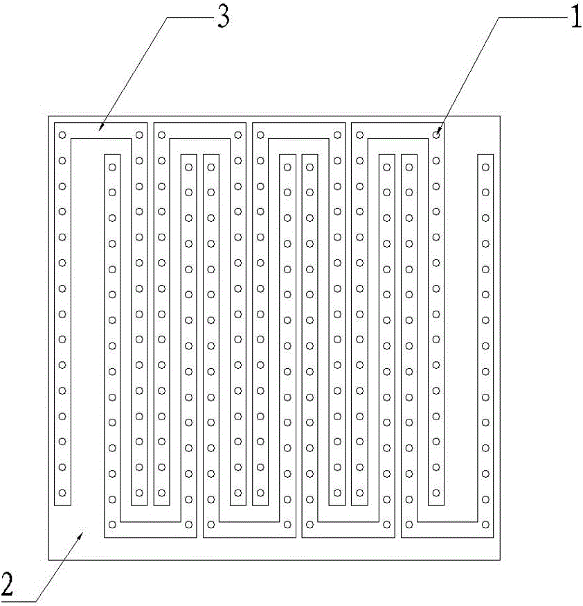
[0033] Such as figure 1 As shown, a forming mold for a heat-insulating formwork for a steel cage, a plurality of mold grooves 3 are arranged in the lower mold 2 of the forming mold, the distances between the mold grooves 3 are equal, and a number of cylindrical mold rods 1 are arranged at equal intervals in the mold , the cylindrical mold rods 1 are located on the center line of the mold and arranged at equal intervals along the length direction of the mold.

[0034] The die grooves 3 are arranged staggeredly in a U shape in the die as a whole.

[0035] The cylindrical mold rod 1 is threadedly connected with the mold cavity 3, and the bottom of the mold cavity 3 is provided with a dislocation sealing plate. The threaded holes on the bottom are in the same position.

[0036] When the dislocation sealing layer moves the threaded hole is covered, and when the dislocation sealing layer returns, the threaded hole is exposed.

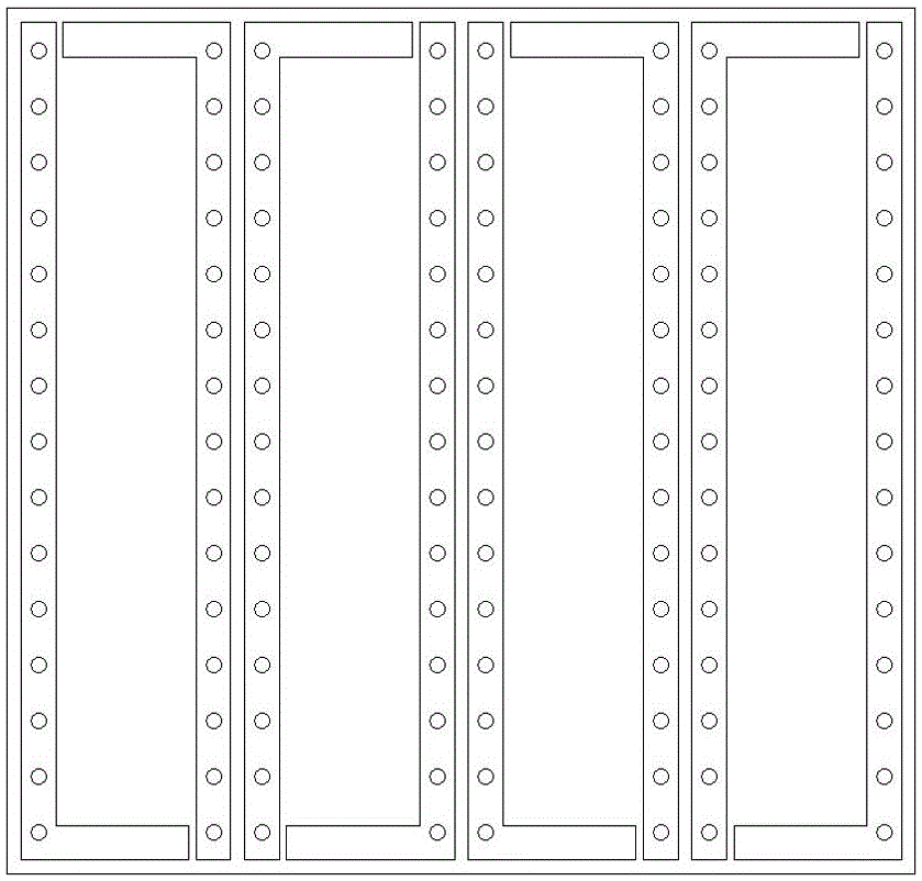
[0037] Die groove can also be as figure 2 The whol...

Embodiment 2

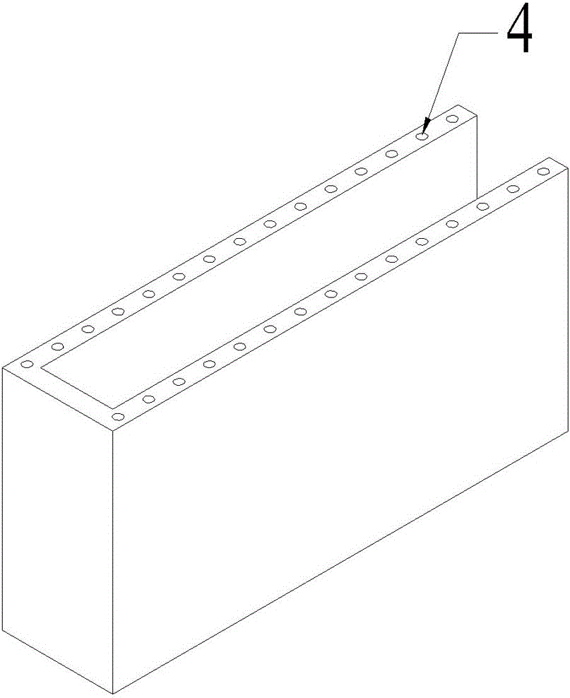
[0039] A thermal insulation formwork for a steel cage. The side wall of the thermal insulation formwork for a steel cage is provided with a cantilever (not shown in the figure), and a vertical tubular air hole 4 is opened on the side wall of the thermal insulation formwork for a steel cage.

[0040] The cantilever is a protruding claw set on the inner wall of the thermal insulation formwork for the steel cage. The rear end of the protruding claw is inserted and filled in the opening on the side wall of the thermal insulation formwork for the steel cage. The protruding claw is precast concrete Prongs.

[0041] The cantilever is a steel mesh sheet with the upper surface of the insulation formwork for the reinforcement cage. One end of the reinforcement mesh sheet is fixedly connected with the insulation formwork for the reinforcement cage, and the other end of the reinforcement mesh sheet is bent. Bending and protruding between two insulation formwork shells for steel cages, and...

Embodiment 3

[0044] A kind of construction method that utilizes the reinforcing cage in embodiment two to use thermal insulation formwork, carry out following steps:

[0045] 1) After the reinforcement cage of the wall column is firmly connected with the reinforcement cage protruding from the foundation or the floor, the reinforcement cage is glued to the side of the reinforcement cage with a thermal insulation formwork to form an insulation wall that is ringed outside the steel reinforcement. The cantilever faces of the formwork are set opposite to each other and extend into the reinforcement cage;

[0046] 2) When the masonry height of the thermal insulation formwork is greater than 25cm, conventionally set supports and railings on the outside of the thermal insulation wall formed by the thermal insulation formwork;

[0047] 3) Pump concrete into the insulation wall and pour it compactly. After the concrete hardens, remove the alignment railings and support bars.

[0048] Step 2) When the...


PUM


Abstract

The invention relates to a heat preservation formwork for a reinforcement cage and a construction method and a forming die of the heat preservation formwork and belongs to the technical field of decoration projects of buildings. The heat preservation formwork is formed through a specially-manufactured die in a die casting mode and is used for heat preservation construction of a shear wall. The side wall of the heat preservation formwork for the reinforcement cage is provided with an outrigger, and the side wall of the heat preservation formwork for the reinforcement cage is provided with vertical tubular ventilation holes. Under the action of the heat preservation formwork, the built shear wall has the advantages that the built shear wall is not likely to be cracked, automatic heat dissipation is achieved, and the service life is prolonged.

Description

technical field [0001] The invention relates to a thermal insulation mold shell, a construction method thereof and a forming mold, and belongs to the technical field of building decoration engineering. Background technique [0002] The shear wall structure uses reinforced concrete wall panels to replace the beams and columns in the frame structure, which can bear the internal forces caused by various loads and can effectively control the horizontal force of the structure. The structure of the force is called the shear wall structure. This structure is widely used in high-rise buildings. [0003] The shear wall structure refers to the structure in which all the main load-bearing structures in the vertical and horizontal directions are structural walls. When the walls are properly positioned in the building, they form a structural system that effectively resists horizontal action and, at the same time, acts as a partition of space. The height of the structural wall is gener...

Claims


Application Information

Patent Timeline
Patent Type & Authority Patents(China)
IPC IPC(8): B28B7/16B28B23/02E04B2/86
CPCB28B7/16B28B23/02E04B2/8605
Inventor 史世英
Owner SUZHOU SHIHAO BUILDING MATERIAL NEW TECH ENG
Why Eureka
Try Eureka