Automatic conveying belt

A technology of conveyor belts and conveyor belts, applied in the field of automation equipment

Inactive Publication Date: 2015-07-22
SHANGHAI CHANGYU COMM TECH CO LTD
View PDF0 Cites 0 Cited by
  • Summary
  • Abstract
  • Description
  • Claims
  • Application Information

AI Technical Summary

Problems solved by technology

[0003] However, the existing conveyor belts may be limited by the geographical location of the factory building, some will be set up in a slope shape, and some will be set up horizontally, but some products need to be transported at a fixed angle on the conveyor belt, so the existing conveyor belt needs to be improved

Method used


Image

  • Automatic conveying belt
  • Automatic conveying belt
  • Automatic conveying belt

Examples


Embodiment Construction

[0024] The following are specific embodiments of the present invention and in conjunction with the accompanying drawings, the technical solutions of the present invention are further described, but the present invention is not limited to these embodiments.

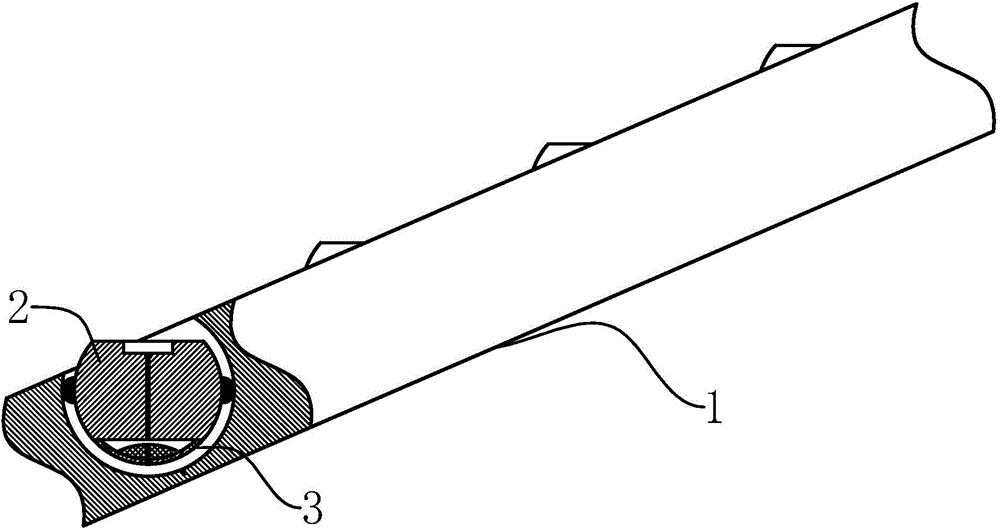
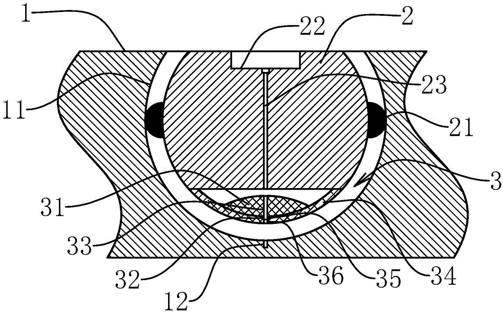
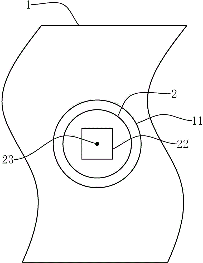
[0025] Such as Figure 1-3 As shown, an automatic conveyor belt of the present invention includes a conveyor belt 1. The conveyor belt 1 is provided with a groove 11 on the conveying surface. 2. A counterweight device 3 is detachably connected to the bottom of the stage 2, and the stage 2 and the counterweight device 3 form a spherical body larger than a hemisphere. A number of balls 21 are arranged on the spherical surface of the stage 2, and the balls 21 is against the groove surface of the groove 11, the top of the stage 2 has a circular stage 2, and the stage 2 has a loading groove 22 for positioning, and can be adjusted by adjusting the counterweight device 3 Adjust the orientation of the notch of the loading slot 22...


PUM


Abstract

The invention provides an automatic conveying belt, and belongs to the technical field of automatic equipment. The purpose of conveying an existing product at a fixed angle on a conveying belt in the prior art is achieved. The automatic conveying belt comprises a conveying belt body, a groove is formed in the conveying surface, the surface of the groove is a spherical crown surface, and the automatic conveying belt further comprises a carrying table arranged inside the groove. A counterweight device is detachably connected to the bottom of the carrying table, the carrying table and the counterweight device form an incomplete-sphere body larger than a hemisphere, multiple rolling balls are arranged on the spherical surface of the carrying table and abut against the surface of the groove, a carrying tabletop is formed at the top of the carrying table and provided with a carrying groove, and the direction of an opening of the carrying groove can be adjusted through adjusting the counterweight device. A product is placed on the carrying tabletop or placed into the carrying groove; because the counterweight device is connected to the bottom of the carrying table, the counterweight device and the rolling balls are matched to make the carrying table form a fixed angle; the counterweight device can be adjusted and is matched with the rolling balls to achieve adjustment in any direction.

Description

technical field [0001] The invention belongs to the technical field of automation equipment and relates to an automation conveyor belt. Background technique [0002] In the middle of the 17th century, the United States began to use aerial cableways to convey bulk materials; in the middle of the 19th century, conveyor belt conveyors of various modern structures appeared one after another. In 1868, belt conveyors appeared in the UK; in 1887, screw conveyors appeared in the United States; in 1905, steel belt conveyors appeared in Switzerland; in 1906, inertial conveyors appeared in the UK and Germany. Since then, the conveyor belt conveyor has been continuously improved under the influence of technological progress in machinery manufacturing, electrical machinery, chemical industry and metallurgical industry. An integral part of the mechanization and automation of material handling systems. [0003] However, the existing conveyor belts may be limited by the geographical locat...

Claims


Application Information

Patent Timeline
Patent Type & Authority Applications(China)
IPC IPC(8): B65G15/58
CPCB65G15/58
Inventor 陈树丽
Owner SHANGHAI CHANGYU COMM TECH CO LTD
Why Eureka
Try Eureka