Method for producing float glass and apparatus for producing float glass

A float glass and a manufacturing method technology, which are applied in the fields of float glass manufacturing and float glass manufacturing devices, can solve problems such as difficulty in reducing the temperature fluctuation range, and achieve the effect of reducing the temperature fluctuation range

Active Publication Date: 2015-07-22
ASAHI GLASS CO LTD
View PDF4 Cites 4 Cited by
  • Summary
  • Abstract
  • Description
  • Claims
  • Application Information

AI Technical Summary

Problems solved by technology

[0007] Conventionally, it has been difficult to simultaneously reduce the range of temperature fluctuations at multiple locati

Method used


Image

  • Method for producing float glass and apparatus for producing float glass
  • Method for producing float glass and apparatus for producing float glass
  • Method for producing float glass and apparatus for producing float glass

Examples


Embodiment

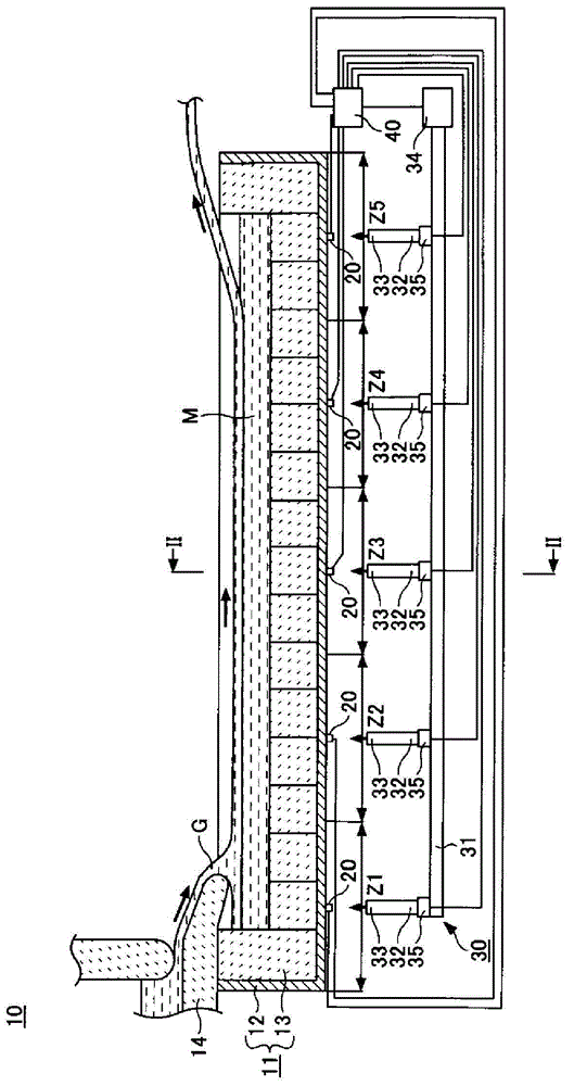
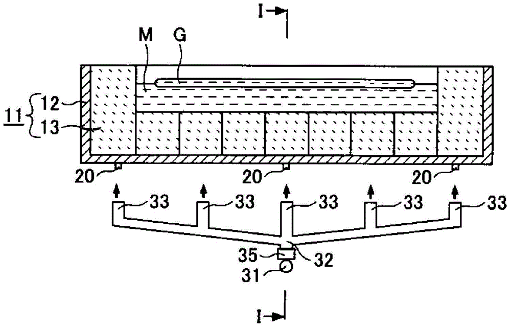
[0068] In Example 1, using figure 1 and figure 2 The float glass manufacturing apparatus 10 shown manufactures the float glass of an alkali-free glass. Air is used as the fluid, an air fan is used as the fluid supply part 34 , and an opposed blade damper is used as the flow rate adjustment part 35 . The rotation speed of the air fan and the rotation angle of the rotation shaft of each opposing blade damper are controlled so that the deviation between the temperature measured by the predetermined temperature sensor and the set temperature becomes zero.

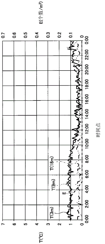
[0069] On the other hand, in Comparative Example 1, float glass was produced in the same manner as in Example 1 except that the rotation angle of the rotation shaft of each opposing vane damper was constant. That is, in order to make the deviation between the temperature measured by the predetermined temperature sensor and the set temperature zero, only the rotation speed of the air fan is controlled.

[0070] image 3 It...


PUM


Abstract

The invention provides a method for producing float glass and an apparatus for producing the float glass. The method for producing the float glass comprises a molding step that molten glass flows on a molten metal in a bath groove to form a plate-shaped glass tape. In the molding step, a lower wall part of the bath groove is cooled by means of a main pipe, branch pipes and nozzles to blow and send a fluid to the lower surface of the bath groove, midways of the various branch pipes are provided with flow adjusting parts for adjusting flow of the fluid, the lower wall part is provide with a plurality of temperature adjusting areas which independently adjust temperature by utilizing the flow adjusting parts, and at least one temperature sensor is disposed in each of the temperature adjusting area. In the molding step, the flow adjusting parts are controlled according to measuring temperature of the at least one temperature sensor disposed in the corresponding temperature adjusting area.

Description

technical field [0001] The invention relates to a float glass manufacturing method and a float glass manufacturing device. Background technique [0002] A float glass manufacturing apparatus has a bath for containing molten metal, continuously supplies molten glass onto the molten metal in the bath, and forms the molten glass into a plate-shaped glass ribbon on the molten metal (for example, refer to Patent Document 1). The glass ribbon gradually hardens while flowing over the surface of the molten metal. The glass ribbon is drawn from the molten metal in the downstream region of the bath and sent to the lehr. The glass ribbon has a flat part between both side edge parts. Since both side edge parts of a glass ribbon are thicker than the flat part of a glass ribbon, they are cut off after annealing. Thereby, the float glass whose board thickness is substantially uniform can be obtained. [0003] The bathtub includes a metal case and a plurality of bricks covering the insi...

Claims


Application Information

Patent Timeline
IPC IPC(8): C03B18/02C03B18/16C03C3/089C03C3/085C03C3/087
CPCC03B18/16C03B18/18C03C3/085
Inventor 稻井要介渡部恵大泷口哲史多久和茂良
Owner ASAHI GLASS CO LTD
Why Eureka
Try Eureka