A linkage control box

A control box and linkage technology, applied in the field of control boxes, can solve the problems of cracking of the control box, heavy weight, inability to meet the requirements of the driver's operating comfort, etc., and achieve the effect of prolonging the service life

Active Publication Date: 2017-04-12
XCMG CONSTR MACHINERY
View PDF4 Cites 0 Cited by
  • Summary
  • Abstract
  • Description
  • Claims
  • Application Information

AI Technical Summary

Problems solved by technology

[0002] The control box of construction machinery cab is mainly used to install hydraulic control valves, electrical control components, brake components, etc. Most of the control boxes of traditional loaders are fixed on the bottom frame of the cab by bolts. When drivers of different sizes operate the machine, they need to Adjust the front, back and height of the seat. At this time, the fixed-position joystick cannot meet the requirements of all drivers for operating comfort; in view of the above reasons, some high-end loaders with electronically controlled gearboxes have placed the control elements in the control box. Internally, the control box is designed as a structure linked with the seat. Because the electric control handle is light in weight and small in size, the linked control box will not affect its service life due to vibration; It is heavy, and it is easy to cause the control box to crack due to vibration when it is suspended on the outside of the seat and linked with it

Method used


Image

  • A linkage control box
  • A linkage control box
  • A linkage control box

Examples


Embodiment Construction

[0021] In order to enable those skilled in the art to better understand the solution of the present invention, the present invention will be further described in detail below in conjunction with the accompanying drawings and specific embodiments.

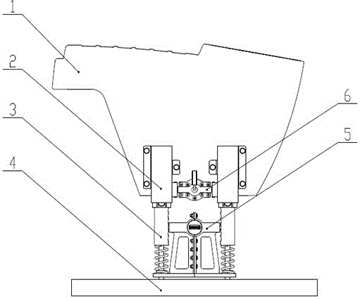
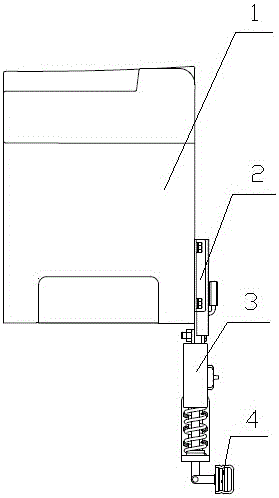
[0022] Such as figure 1 with figure 2 As shown, the linkage control box of the present invention includes a control box housing 1, a height adjustment slide rail 2, a shock absorbing mechanism 3, a front and rear adjustment slide rail 4, a shock absorbing locking mechanism 5, a slide rail locking mechanism 6, etc. The control box shell 1 described above is connected with the cab seat; the front and rear adjusting slide rails 4 described above are connected with the bottom frame of the cab.

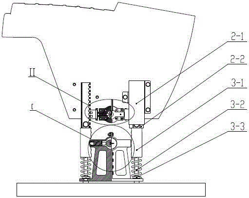
[0023] Such as image 3 As shown, the height adjustment slide rail 2 includes an upper slide rail 2-1 and a lower slide rail 2-2; the upper slide rail 2-1 is welded by a track, a mounting plate, and a guide groove, and is aligned with the ope...


PUM


Abstract

The invention discloses a linkage-type maneuvering box. The linkage-type maneuvering box comprises a maneuvering box shell, a height adjusting sliding rail and a damping mechanism. The maneuvering box shell is connected with a seat in a driving cab. The height adjusting sliding rail comprises an upper sliding rail and a lower sliding rail. The upper sliding rail is fixedly connected with the maneuvering box shell. The upper sliding rail slides in the lower sliding rail to achieve the linear motion in the vertical direction of the maneuvering box. The damping mechanism comprises a damper, a spring and a fixed nut. The upper end face of the damper is welded with an installing plate with open holes, and the installing plate is fixedly connected with the lower sliding rail through a bolt. The spring is connected below the damper and is fastened through the fixed nut. According to the solution of supporting and damping, a sliding mechanism is used to achieve moving of the maneuvering box in the forward and backward direction and in the up and down direction, the parallel structure of the damper and the spring is used to achieve supporting and damping of the maneuvering box, and the multi-step adjustment of a double dead lock mechanism is used to satisfy the demand on maneuvering comfort of a driver and the demand of providing constant support force to the maneuvering box.

Description

technical field [0001] The invention relates to a loader, in particular to a control box linked with a cab seat. Background technique [0002] The control box of construction machinery cab is mainly used to install hydraulic control valves, electrical control components, brake components, etc. Most of the control boxes of traditional loaders are fixed on the bottom frame of the cab by bolts. When drivers of different sizes operate the machine, they need to Adjust the front, back and height of the seat. At this time, the fixed position of the joystick cannot meet the requirements of all drivers for operating comfort; in view of the above reasons, some high-end loaders with electronically controlled gearboxes have placed the control elements in the control box. Internally, the control box is designed as a structure linked with the seat. Because the electric control handle is light in weight and small in size, the linked control box will not affect its service life due to vibra...

Claims


Application Information

Patent Timeline
Patent Type & Authority Patents(China)
IPC IPC(8): E02F9/16
Inventor 李喆路振坡王振清王猛刘昕晁靖吴闯于振波
Owner XCMG CONSTR MACHINERY
Why Eureka
Try Eureka