
Thin bag coded lock

A combination lock and luggage technology, which is applied in the field of locks, can solve the problems of occupying luggage space, weakening the structural strength of the recessed part, and failing to protect the combination lock, etc., and achieves the effects of simple and convenient operation, increased application range, and reduced thickness

Active Publication Date: 2015-07-22
YIFENG MFG
View PDF6 Cites 2 Cited by
  • Summary
  • Abstract
  • Description
  • Claims
  • Application Information

AI Technical Summary

Problems solved by technology

Because the thickness of the existing combination lock is relatively thick, when the combination lock is installed in the recessed part of the box body, the recessed part must have sufficient depth, so that the combination lock can be completely hidden in the concave part, and then the effective However, if the depth of the concave part is designed to be deep, it will inevitably occupy the space in the bag, thereby reducing the storage space in the bag, and will also weaken the structural strength of the concave part, thereby weakening the structural strength of the entire bag. To solve the above problems, it is necessary to design the recessed part of the case and bag shallower, which brings another problem. When the existing coded lock is installed in the shallow recessed part, the recessed part cannot completely hide the coded lock, that is, the coded lock. A part is exposed in the recessed part, so that the shallower recessed part cannot protect the function of the combination lock, and the existing combination lock generally realizes the automatic unlocking of the combination lock by pressing the pushed side part, and the shallower recess The part reduces the contact area between the pusher and the finger, which is very inconvenient to operate the pusher

Method used


Image

  • Thin bag coded lock
  • Thin bag coded lock
  • Thin bag coded lock

Examples


Embodiment Construction

[0059] The present invention is further described in conjunction with the following examples.

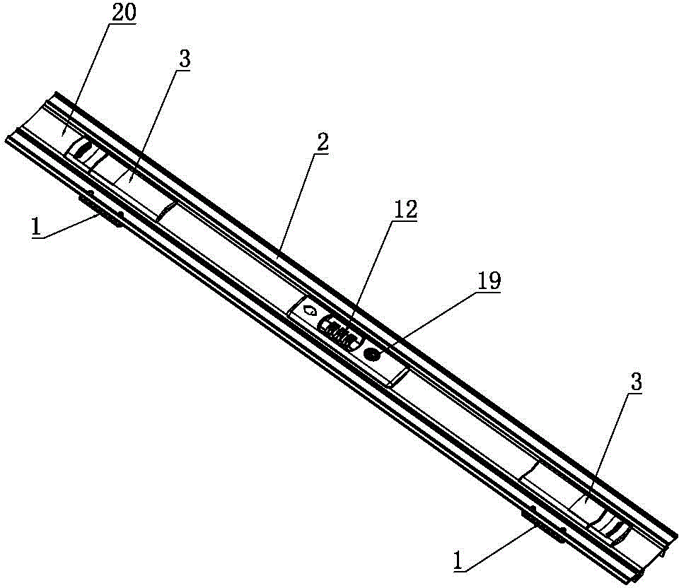
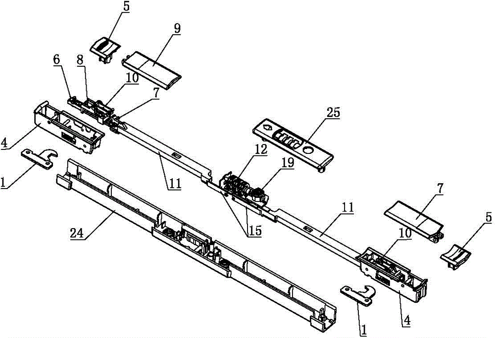
[0060] The specific embodiment of a kind of thin luggage combination lock of the present invention, as figure 1 and figure 2As shown, it includes a combination lock mechanism, a lock mechanism 3 and a lock hook 1. The combination lock mechanism and the lock mechanism 3 are all fixed on the box body 2 on one side of the luggage, and the lock hook 1 is fixed on the box body on the other side of the luggage bag. 2. Since the box body 2 is provided with a recessed portion 20, the combination lock mechanism and the locking mechanism 3 are both built into the recessed portion 20, and a connecting rod 11 is provided between the combination lock mechanism and the locking mechanism 3.

[0061] Concretely, the luggage combination lock of the present invention comprises two locking mechanisms 3, and the two locking mechanisms 3 are respectively arranged at the two ends of the luggage combina...


PUM


Abstract

A thin bag coded lock structurally comprises lock catch mechanisms and a coded lock mechanism. Each lock catch mechanism comprises a bottom shell, a push rod, a locking block, a lock catch and a face shell. The face shells and the locking blocks are rotationally connected to the bottom shells. In the unlocking process, the coded lock mechanism removes abutting operation on the locking blocks, push mechanisms are pushed to drive the locking blocks to rotate through the push rods, clamping hooks are disengaged from clamping grooves, the face shells rotate and push the lock catches to slide, and the lock catches are disengaged from the locking hooks. Due to the fact that the push mechanisms and the locking blocks are disengaged, the push mechanisms and the locking blocks are arranged at the two ends of the push rods in parallel, the thickness of the coded lock is reduced, the coded lock can be completely hidden in a shallow recessed part of a bag, the application range of the coded lock is enlarged, the transmission relationship among each face shell, a connecting rod and the corresponding push rod can be achieved through the corresponding locking block, the structure of the coded lock is compact, and the thickness of the coded lock is further reduced. In addition, the push mechanisms slide horizontally by shifting the positive upper faces of the push mechanisms and operation is easy and convenient.

Description

technical field [0001] The invention relates to the technical field of locks, in particular to a thin combination lock for luggage which is suitable for being installed in a shallow recess of a box body. Background technique [0002] For the convenience and safety of traveling, luggage coded locks are generally provided on luggage, and luggage coded locks generally use digital codes or keys to control the movement of the inner lock of the coded lock, so that the lock buckle and the lock hook on the luggage are buckled or disengaged. , so as to realize the locking or unlocking of the luggage, the password lock of the luggage is easy to operate, safe and reliable, and has a wide range of applications. [0003] Since the combination lock is a precision part, it is easy to be damaged, and it is difficult to repair after damage, thereby reducing the safety performance of the bag. Therefore, the bag is generally provided with a recessed part, and the combination lock is set in th...

Claims


Application Information

Patent Timeline
IPC IPC(8): E05B65/52E05B37/20
Inventor 赖秀兴
Owner YIFENG MFG
Learn More