a diaphragm pump

A diaphragm pump and diaphragm technology, which is applied in the direction of pumps, pump components, variable capacity pump components, etc., can solve the problems of diaphragm pump efficiency loss, low diaphragm life, slow valve response, etc., to reduce air flow fluctuations and improve stability Improvement of performance and response speed

Active Publication Date: 2017-11-14
李新华
View PDF8 Cites 0 Cited by
  • Summary
  • Abstract
  • Description
  • Claims
  • Application Information

AI Technical Summary

Problems solved by technology

[0005] The technical problem to be solved by the present invention is the problem of low life of the diaphragm caused by increasing the speed of the diaphragm pump in order to reduce air flow pulsation in the collection of air particulate matter, and the problem of efficiency loss of the diaphragm pump caused by the slow response of the valve plate

Method used


Image

  • a diaphragm pump
  • a diaphragm pump
  • a diaphragm pump

Examples


Embodiment 1

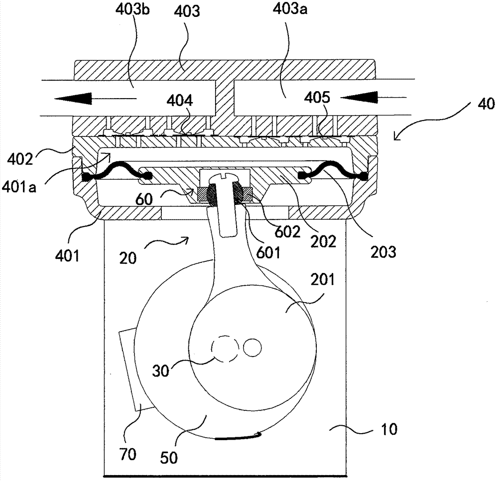
[0019] Embodiment one, this embodiment proposes a kind of diaphragm pump, such as figure 1 As shown, it includes a casing 10, a diaphragm pumping structural assembly 20 arranged in the casing 10, a motor for driving the diaphragm pumping structural assembly, and a pump head assembly 40 arranged at one end of the casing 10, the An eccentric wheel 50 is fixedly arranged on the output shaft 30 of the motor, and the diaphragm suction structure assembly 20 includes a connecting rod 201 eccentrically connected with the eccentric wheel 50, a joint bearing 60 connected with the connecting rod 201, and a joint bearing 60. The connected circular pressing piece 202 and the annular diaphragm 203, the inner ring edge of the diaphragm 203 is pressed and fixed by the pressing piece 202, the outer ring edge is fixed with the pump head assembly 40, and the pump head The assembly 40 includes a pump head seat 401, a valve seat 402 arranged on the upper surface of the pump head seat 401, and a pu...

Embodiment 2

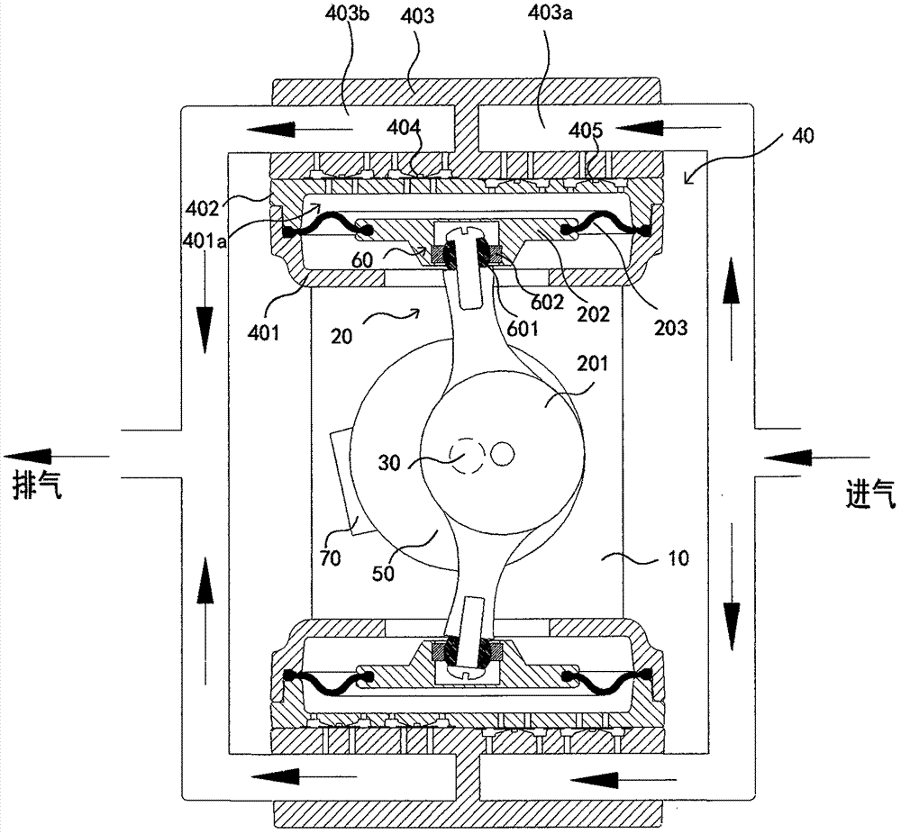
[0026] Embodiment 2, based on a kind of diaphragm pump in embodiment 1, this embodiment proposes another kind of diaphragm pump, this diaphragm pump is a double-headed pump, such as image 3 As shown, it includes a casing 10, a motor output shaft 30, a diaphragm suction structure assembly 20 symmetrically arranged in the casing, pump head assemblies 40 respectively arranged at both ends of the casing 10, and the output shaft of the motor 30 An eccentric wheel 50 is fixedly arranged on the top, taking the diaphragm pumping structural assembly 20 on one side as an example, the diaphragm pumping structural assembly 20 includes a connecting rod 201 connected eccentrically to the eccentric wheel, connected to the connecting rod 201 The joint bearing 60, the circular pressing piece 202 connected with the joint bearing 60, and the annular diaphragm 203, the inner ring edge of the diaphragm 203 is pressed and fixed by the pressing piece 202, and the outer ring edge and the diaphragm T...


PUM


Abstract

The present invention proposes a diaphragm pump, which includes a casing, a diaphragm suction structure assembly, a motor, and a pump head assembly. An eccentric wheel is fixedly arranged on the output shaft of the motor. The diaphragm suction structure assembly includes a connecting rod, and the pump head assembly. The joint bearing connected by the connecting rod, the circular pressing plate connected with the joint bearing, and the annular diaphragm, the inner ring edge of the diaphragm is fixed by pressing the pressing plate, and the outer ring edge is fixed with the pump head assembly , the pump head assembly includes a pump head seat, a valve plate seat, a pump head upper cover, a plurality of air intake check valves are arranged between the air inlet channel and the pump head inner cavity, and the exhaust channel and the pump head inner cavity A plurality of exhaust one-way valves are arranged between them, and the valve plates of the intake one-way valve and the exhaust one-way valve include an annular sealing ring and a circular valve core arranged inside the annular sealing ring, and the circular valve The core is connected with the annular sealing ring through two symmetrical connection parts. The diaphragm pump has a long service life and a large suction negative pressure, and is especially suitable for collecting air particles.

Description

technical field [0001] The invention relates to a diaphragm pump, in particular to a diaphragm pump for air particle collection. Background technique [0002] There are a large number of solid particles of different particle sizes suspended in the ambient air. In the detection of the concentration of suspended particles in the ambient air, the sampler separates PM2.5 from particles of different masses and particle sizes in the air (the particle size is less than or equal to 2.5 microns Particles), then pass the air containing PM2.5 through the filter membrane at a certain flow rate, collect a specific time, PM2.5 is filtered on the filter membrane, and then weigh the filter membrane to remove the background weight of the filter membrane and increase The ratio of the weight of the sample to the total volume collected can be used to obtain the concentration of particulate matter contained in a unit volume of air to evaluate the ambient air quality. The sampler uses the princi...

Claims


Application Information

Patent Timeline
Patent Type & Authority Patents(China)
IPC IPC(8): F04B45/027F04B39/10
Inventor 李新华
Owner 李新华
Why Eureka
Try Eureka