An axial flow pump impeller guide cone

A water guide cone and axial flow pump technology, which is applied to pumps, parts of pumping devices for elastic fluids, pump elements, etc., can solve the problems of no pre-rotation, etc., and achieve the goal of improving speed uniformity and improving impeller efficiency Effect

Active Publication Date: 2017-11-17
JIANGSU UNIV
View PDF5 Cites 0 Cited by
  • Summary
  • Abstract
  • Description
  • Claims
  • Application Information

AI Technical Summary

Problems solved by technology

[0002] Axial flow pump is a very widely used hydraulic mechanical device. It has a wide range of applications in irrigation and drainage, urban water supply and drainage, sewage and long-distance water supply. The impeller of a common axial flow pump includes the following parts: impeller hub body, The blade installed on the impeller hub body, the water guide cone installed at the end of the impeller hub body; the impeller hub, the blade and the water guide cone together form the impeller. In order to ensure that the axial flow pump impeller is in an ideal working state, it is generally required The water flow is evenly distributed, and the inflow has no pre-swirl, etc.; adding a water guide cone at the front of the impeller of the axial flow pump can accelerate the water flow evenly before entering the impeller, and provide the impeller with an evenly distributed inflow without pre-swirl. At the same time, the design is reasonable The water guide cone plays an important role in improving the quality of the inlet flow field of the axial flow pump, improving the uniformity and stability of the velocity; at present, there are few reports on the research on the water guide cone of the axial flow pump impeller, and the research of domestic and foreign scholars mainly focuses on the axial flow pump impeller. Research on the water inlet conditions of flow pumps; Zhu Honggeng, Yuan Shouqi et al. studied the influence of elbow-shaped water inlet channels on the hydraulic performance of vertical axial flow pumps; The hydraulic characteristics of the water channel have been studied, so it is of practical significance to design an excellent water guide cone to provide more uniform and stable inflow conditions for the axial flow pump impeller

Method used


Image

  • An axial flow pump impeller guide cone
  • An axial flow pump impeller guide cone
  • An axial flow pump impeller guide cone

Examples


Embodiment Construction

[0022] The present invention will be further described below in conjunction with accompanying drawing.

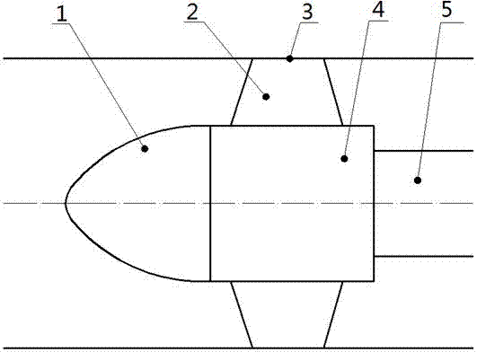
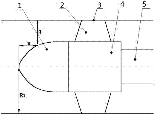
[0023] figure 1 A sectional view of the axial flow guide cone of the impeller of the axial flow pump of the present invention is given, figure 2 The axial sectional view of the water guide cone of the impeller of an ordinary axial flow pump is given.

[0024] Depend on figure 1 , 2 It can be seen that both the water guiding cone of the impeller of the present invention and the traditional water guiding cone of the impeller include the water guiding cone 1, the hub body of the impeller 4, the axial flow blades 2 evenly arranged on the circumference of the hub body, the wall surface of the impeller chamber 3, and the pump shaft 5.

[0025] Take the length L of the water guide cone: L is taken as (0.5~1.0)d h , d h is the diameter of the impeller hub.

[0026] Starting from the head of the water guide cone, calculate the R value corresponding to each x according to the ...


PUM


Abstract

The invention relates to an axial flow pump, in particular to an axial flow pump impeller water-guiding cone. The axial flow pump impeller water-guiding cone comprises a water-guiding cone, impeller blades, a wall face of an impeller chamber, an impeller hub body and a pump shaft. The axial flow pump impeller water-guiding cone is characterized in that the water-guiding cone is arranged at the front portion of an axial flow pump impeller, and a contracting line of the water-guiding cone adopts a fitting curve, so that uniform flowing of fluid in a flow passage of the water-guiding cone is realized. The axial flow pump impeller water-guiding cone has the advantages that velocity-weighted average swirl angle at the outlet section of the water-guiding cone can be decreased, the axial velocity equilibrium of distribution at the outlet section of the water-guiding cone is improved, and the hydraulic efficiency of the impeller is improved.

Description

technical field [0001] The invention relates to an axial flow pump, in particular to an axial flow pump impeller water guide cone. Background technique [0002] Axial flow pump is a very widely used hydraulic mechanical device. It has a wide range of applications in irrigation and drainage, urban water supply and drainage, sewage and long-distance water supply. The impeller of a common axial flow pump includes the following parts: impeller hub body, The blade installed on the impeller hub body, the water guide cone installed at the end of the impeller hub body; the impeller hub, the blade and the water guide cone together form the impeller. In order to ensure that the axial flow pump impeller is in an ideal working state, it is generally required The water flow is evenly distributed, and the inflow has no pre-swirl, etc.; adding a water guide cone at the front of the impeller of the axial flow pump can accelerate the water flow evenly before entering the impeller, and provid...

Claims


Application Information

Patent Timeline
Patent Type & Authority Patents(China)
IPC IPC(8): F04D29/18
CPCF04D29/181
Inventor 杨敏官孟宇倪丹李忠
Owner JIANGSU UNIV
Why Eureka
Try Eureka