Connecting rod mutual sealing water distribution structure

A technology of water diversion structure and connecting rod, which is applied in the direction of valve details, multi-way valves, engine components, etc., can solve the problems of large operating resistance and inconvenient operation, and achieve the effect of small operating force, simple structure, and labor-saving operating space

Active Publication Date: 2015-07-22
FUJIAN XIHE SANITARY WARE TECH
View PDF5 Cites 4 Cited by
  • Summary
  • Abstract
  • Description
  • Claims
  • Application Information

AI Technical Summary

Problems solved by technology

[0002] At present, the water diversion structure of the water separators on the existing market mostly adopts the conventional lifting type or the rotating method of the movable and fixed pieces made of ceramics for water diversion; the above two methods have the same defect: the operation resistance is large ;Pull-type water diversion structure, in the process of pulling water diversion, its plugging parts usually have to overcome the water pressure at the water outlet port, and the required operating force is usually greater than the pressure of the water flow, and there is no pressure dividing device. For the elderly and children, the operation is extremely inconvenient; the rotating water diversion structure mainly sets the water diversion port between the moving and fixed pieces, and makes the water diversion port correspond to the water inlet during the rotation process to realize the water diversion process, but its operation It still requires a large knob force to overcome the impact of the water flow, and a large operating force is also required to realize the water separation; therefore, the existing water separation structure is difficult to meet the needs of the operation

Method used


Image

  • Connecting rod mutual sealing water distribution structure
  • Connecting rod mutual sealing water distribution structure
  • Connecting rod mutual sealing water distribution structure

Examples


Embodiment approach

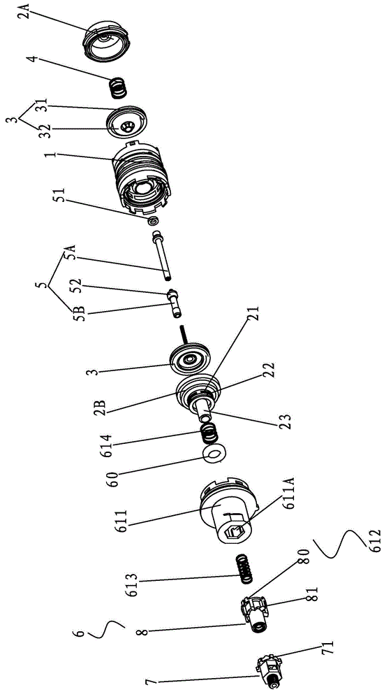
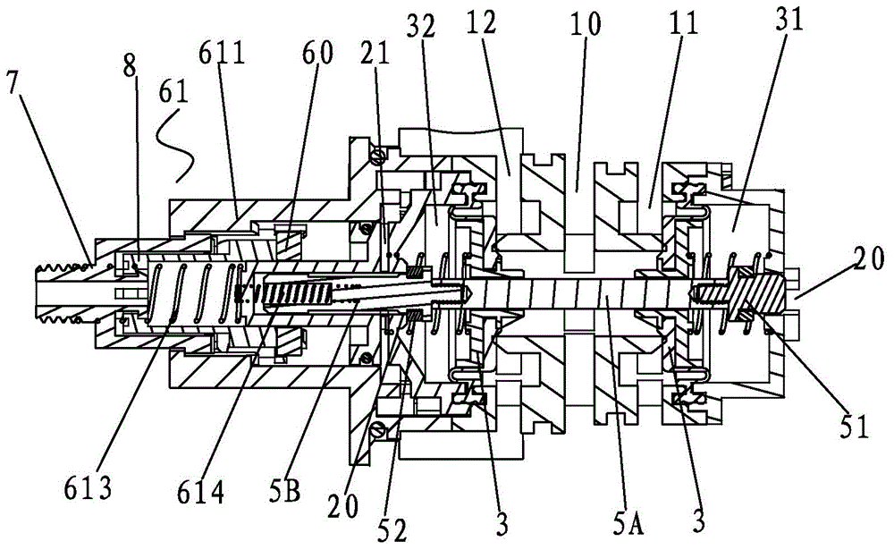
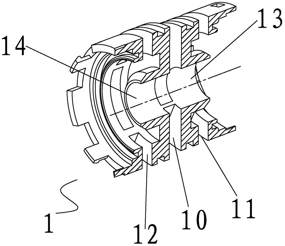
[0037] Specific implementation methods, such as Figure 1 to Figure 4 As shown, a connecting rod inter-sealing water diversion structure according to the present invention mainly includes the following components: body 1, first and second covers 2A, 2B, first and second connecting rods 5A, 5B, First and second blocking units 51, 52, at least two sealing deformation units 3, return spring 4, magnetic unit 60, housing 611, springs 613, 614, pressing unit 7 and rotating push rod 8;

[0038] When assembling, for the water-dividing structure part, first, the first and second blocking units 51 and 52 are respectively attached to the outer peripheries of the first and second linkage rods 5A and 5B; then the first and second blocking units 51 , 52 are also sleeved on the two connecting rods 5 respectively, and then the first connecting rod 5A is passed through the body 1, so that the deformation part 32 of the sealing deformation unit 3 is blocked in the water inlet channels 13, 14, a...


PUM


Abstract

The invention discloses a connecting rod mutual sealing water distribution structure which comprises a body, a first cover body and a second cover body. The first cover body and the second cover body are arranged at the two ends of the body respectively. The body is provided with a water inlet cavity and at least two water outlets. The connecting rod mutual sealing water distribution structure further comprises at least two sealing deformation units and a connecting rod mutual sealing mechanism. The sealing deformation units are arranged between the body and the two cover bodies respectively and seal and plug the two sides of the water inlet cavity respectively. The connecting rod mutual sealing mechanism comprises a linkage rod penetrating through the two cover bodies and the body, the linkage rod is provided with a first sealing and plugging unit and a second sealing and plugging unit which are used for sealing and plugging the two cover bodies, and the first sealing and plugging unit is arranged at the end of the linkage rod. The connecting rod mutual sealing water distribution structure is simple in structure and easy to achieve, the operation force is effectively reduced through the connecting rod mutual sealing structure, one-axis movement and bidirectional control are achieved, and the effect of saving labor and operation space is achieved; by means of the magnetic force brake principle, friction does not exist between the operation part and the linkage rod, resistance is reduced, and the demand for labor saving in the operation process can be easily met.

Description

technical field [0001] The invention relates to the bathroom industry, in particular to a water-dividing structure with connecting rods mutually sealed. Background technique [0002] At present, the water diversion structure of the water separators on the existing market mostly adopts the conventional lifting type or the rotating method of the movable and fixed pieces made of ceramics for water diversion; the above two methods have the same defect: the operation resistance is large ;Pull-type water diversion structure, in the process of pulling water diversion, its plugging parts usually have to overcome the water pressure at the water outlet port, and the required operating force is usually greater than the pressure of the water flow, and there is no pressure dividing device. For the elderly and children, the operation is extremely inconvenient; the rotating water diversion structure mainly sets the water diversion port between the moving and fixed pieces, and makes the wat...

Claims


Application Information

Patent Timeline
Patent Type & Authority Applications(China)
IPC IPC(8): F16K11/048F16K31/53
CPCF16K11/161F16K31/086F16K31/385F16K31/52416F16K31/52491F16K11/022F16K11/048F16K31/0641F16K31/44F16K31/53
Inventor 林孝发林孝山刘启乔邓小清周林
Owner FUJIAN XIHE SANITARY WARE TECH
Why Eureka
Try Eureka