
Magnetorheological fluid power testing device

A technology of magnetorheological fluid and dynamometer device, which is applied in the field of dynamometer, can solve the problems of insensitive dynamometer response and easy loss, etc., and achieve the effects of sensitive response, convenient maintenance and small size

Active Publication Date: 2015-07-22
SHANGHAI UNIV OF ENG SCI
View PDF4 Cites 2 Cited by
  • Summary
  • Abstract
  • Description
  • Claims
  • Application Information

AI Technical Summary

Problems solved by technology

[0004] The technical problem to be solved by the present invention is to provide a magneto-rheological fluid dynamometer, which can better make up for the shortcomings of the existing dynamometers, which are not sensitive enough to respond and are easy to wear and tear, and can be well integrated with the electronically controlled display unit Connection, easy to use computer for precise control

Method used


Image

  • Magnetorheological fluid power testing device
  • Magnetorheological fluid power testing device
  • Magnetorheological fluid power testing device

Examples


Embodiment Construction

[0035] The present invention will be further described below in conjunction with accompanying drawing.

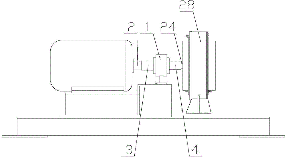
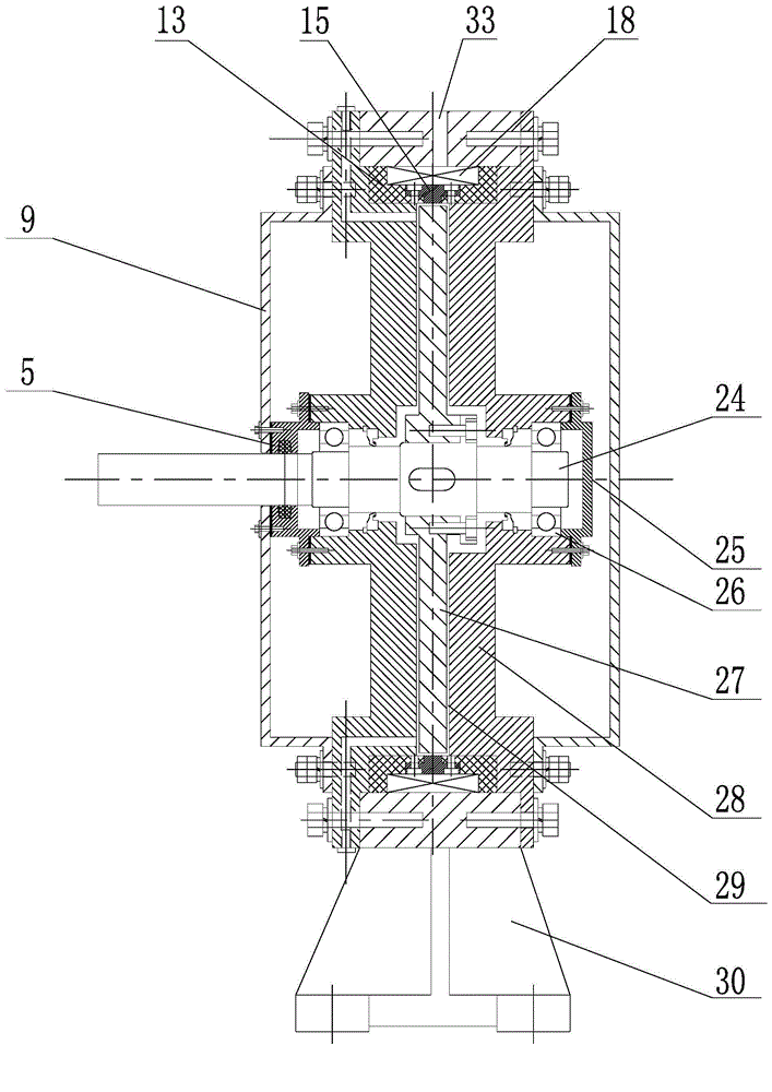
[0036] The turntable 27 is coaxially fixed on the input shaft 24 arranged horizontally and horizontally. The casing 2 is arranged outside the turntable 27. The casing 28 is installed on the input shaft 24 through the bearing 26. One end of the input shaft 24 extends out of the casing 28, and the extension end is on the Equipped with a torque sensor 1, the protruding end is connected to the power shaft 2 to be tested through a pair of flanges 3 and 4, and the input shaft 24 and the power shaft 2 to be tested are respectively installed on the left and right flanges 3 and 4 through flat keys , The torque sensor 1 is arranged between the two flanges 3 and 4, and the three are locked together by radial bolts.

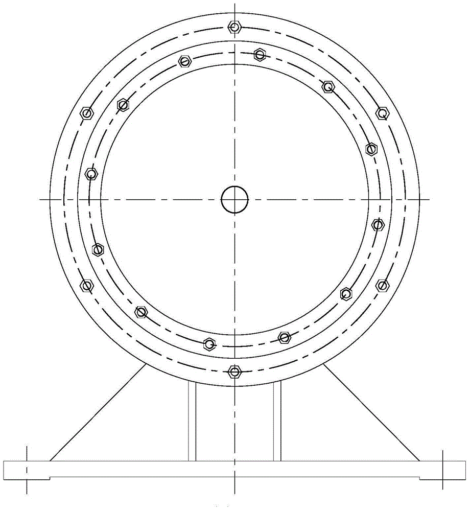
[0037] The housing 28 includes two disc-shaped housings 10 arranged vertically and coaxially and a ring-shaped housing 17 disposed between the two disc-shaped housings 10...


PUM


Abstract

The invention provides a magnetorheological fluid power testing device. A rotating plate is coaxially fixed to an input shaft which is horizontally and transversely arranged. A shell is arranged outside the rotating plate. The shell is arranged on the input shaft through a bearing. One end of the input shaft extends out of the shell. A rotating torque sensor is arranged at the extending end. A circle of coil is arranged in the shell in the circumferential direction of the rotating plate. Yokes are arranged on the end faces of the two ends of the coil respectively. A magnetic isolation ring is arranged between the two yokes. The rotating plate is located in an inner hole of the magnetic isolation ring. A supporting base is arranged at the bottom of the shell. A circulation water cooling water jacket is arranged outside the shell. A temperature sensor, the coil and the rotating torque sensor are arranged in the circulating water cooling jacket. A to-be-tested power shaft and the temperature sensor are connected with an electronic control display unit through signals respectively. The magnetorheological fluid power testing device is flexible in reaction, the load on the rotating plate can be changed by powering on the coil, connection with the electronic control display unit is facilitated, and the test is accurately controlled through a computer; magnetorheological fluid loses magnetic force after shutdown and can be rapidly changed into the liquid shape, the load on the rotating plate is small, and therefore the service life of the device can be prolonged.

Description

technical field [0001] The invention relates to a dynamometer, in particular to a magneto-rheological fluid dynamometer. Background technique [0002] Dynamometer, also called dynamometer, is mainly used to test the output power of motors, engines, etc., and can also be used to test the transmission power of loading equipment such as gearboxes, reducers, and gearboxes. Mainly divided into hydraulic dynamometer, eddy current dynamometer, electric dynamometer. The most common of these is the electric dynamometer, which uses an electric motor to measure the torque output on various powered mechanical shafts, which is combined with the rotational speed to determine power. Because the power machinery to be measured may have different speeds, the motor used as an electric dynamometer must be a motor that can smoothly adjust the speed. At present, DC dynamometer, AC dynamometer and eddy current dynamometer are widely used. [0003] Existing various dynamometers usually have a ce...

Claims


Application Information

Patent Timeline
IPC IPC(8): G01L3/24
Inventor 罗一平周峰任红娟吴国庆田鹏飞袁姝罗锦方轶
Owner SHANGHAI UNIV OF ENG SCI
Learn More