Concrete compressive failure stress-strain full curve test device
A technology of breaking stress and testing equipment, which is applied to measuring equipment, using stable tension/pressure to test the strength of materials, instruments, etc., can solve the problems of failure to obtain test results, pressure damage of displacement gauges, displacement of upper and lower ring brackets, etc. problems, to achieve the effect of improving test efficiency and test effect, ensuring plane stability, and ensuring accuracy
- Summary
- Abstract
- Description
- Claims
- Application Information
AI Technical Summary
Problems solved by technology
Method used
Image
Examples
Embodiment 1
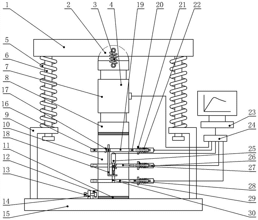
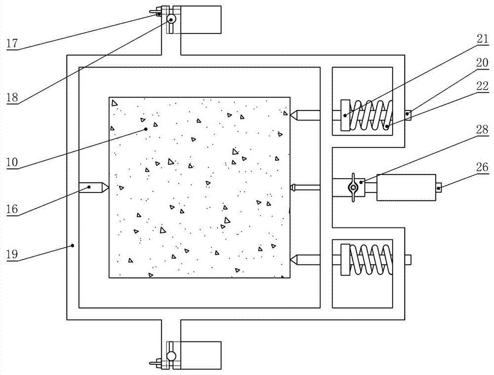
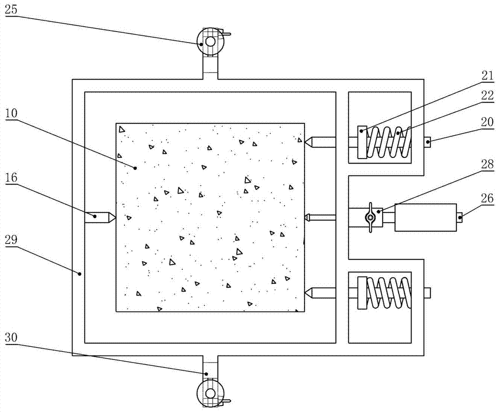
[0040] Embodiment 1: see figure 1 , figure 2 , image 3 , Figure 4 , Figure 5 and Figure 6 , figure 1 The concrete compressive stress-strain full curve testing device in this embodiment includes a loading fixture, a specimen deformation testing fixture and a data acquisition and processing system. Specifically, it consists of top plate 1, ball hinge 2, ball hinge connector 3, force transmission plate 4, spring 5, slide rod 6, load sensor 7, pressure plate 8, pillar 9, test piece 10, rubber pad 11, and L-shaped test piece positioning. Plate 12, position adjustment screw 13, specimen positioning seat 14, bottom plate 15, fixed clamping nail 16, butterfly bolt 17, deformation sensor ejector rod 18, deformation sensor upper bracket 19, movable clamping nail 20, baffle plate 21, Clamping nail compression spring 22, computer 23, controller 24, longitudinal deformation sensor 25, lateral deformation sensor 26, deformation sensor middle bracket 27, lateral deformation sensor...
Embodiment 2
[0044] Example 2: see Figure 7 , the concrete compressive stress-strain full curve test device of the present embodiment is completely the same as that of the embodiment 1 in the loading fixture and data acquisition and processing system, and its specimen deformation test fixture is different from the characteristics of the embodiment 1 in that: in the deformation sensor The bracket fixing frame is provided with a movable clamping nail, and the outside of the right limb is fixedly connected with a movable clamping nail limiting frame. The right side of the frame is fixedly connected to the clamping frame of the lateral displacement meter. The outer frame of the clamping frame corresponds to the top plate of the lateral displacement meter. is the mean value of the two lateral displacement sensors.
Embodiment 3
[0045] Embodiment 3: see Figure 8, this embodiment is exactly the same as Embodiment 1 and Embodiment 2 in terms of the loading fixture and data acquisition and processing system, and its difference from Embodiment 1 and Embodiment 2 is that the lateral deformation sensor is clamped on the limit frame On the outer frame, the top bead of the measuring end of the lateral deformation sensor is pushed against the top plate connecting the two movable clamping nail baffles. The movable clamping nails are connected by shafts, which can ensure the independence of the two movable clamping nails, and can measure the lateral deformation of the specimen at the same time.
PUM
| Property | Measurement | Unit |
|---|---|---|
| particle diameter | aaaaa | aaaaa |
| length | aaaaa | aaaaa |
| diameter | aaaaa | aaaaa |
Abstract
Description
Claims
Application Information
 - R&D
- Intellectual Property
- Life Sciences
- Materials
- Tech Scout
- Unparalleled Data Quality
- Higher Quality Content
- 60% Fewer Hallucinations
Browse by: Latest US Patents, China's latest patents, Technical Efficacy Thesaurus, Application Domain, Technology Topic, Popular Technical Reports.
© 2025 PatSnap. All rights reserved.Legal|Privacy policy|Modern Slavery Act Transparency Statement|Sitemap|About US| Contact US: help@patsnap.com


