
Digital control precision loading mechanism

A loading mechanism and digital control technology, applied in the field of mechanical testing technology and mechanical experiment, can solve the problem of inability to directly calibrate precision sensors, and achieve the effect of expanding the scope of application, flexibility, and high control accuracy

Inactive Publication Date: 2015-07-22
DALIAN NATIONALITIES UNIVERSITY
View PDF7 Cites 4 Cited by
  • Summary
  • Abstract
  • Description
  • Claims
  • Application Information

AI Technical Summary

Problems solved by technology

However, the general loading mechanism also has great limitations in practical applications: it cannot realize the precise quantitative loading of the test material and obtain the mechanical (mechanical) characteristics of the material; it cannot directly calibrate the precision sensor to obtain the calibration of the precision sensor characteristic curve, so it cannot be used in occasions requiring high repeatability

Method used


Image

  • Digital control precision loading mechanism
  • Digital control precision loading mechanism
  • Digital control precision loading mechanism

Examples


Embodiment 1

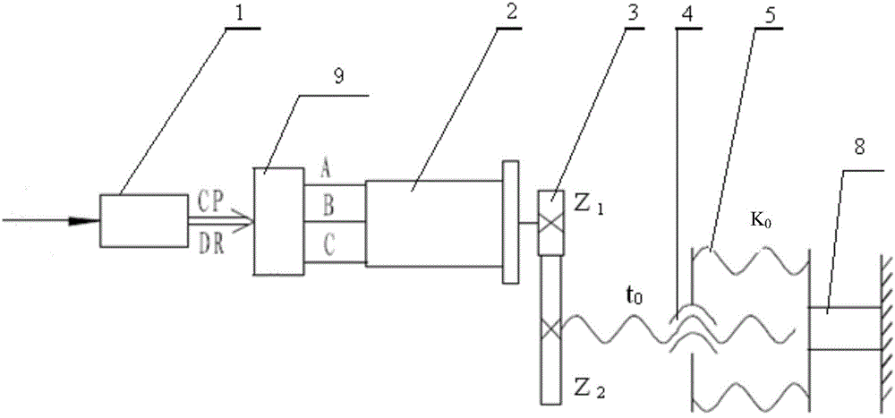
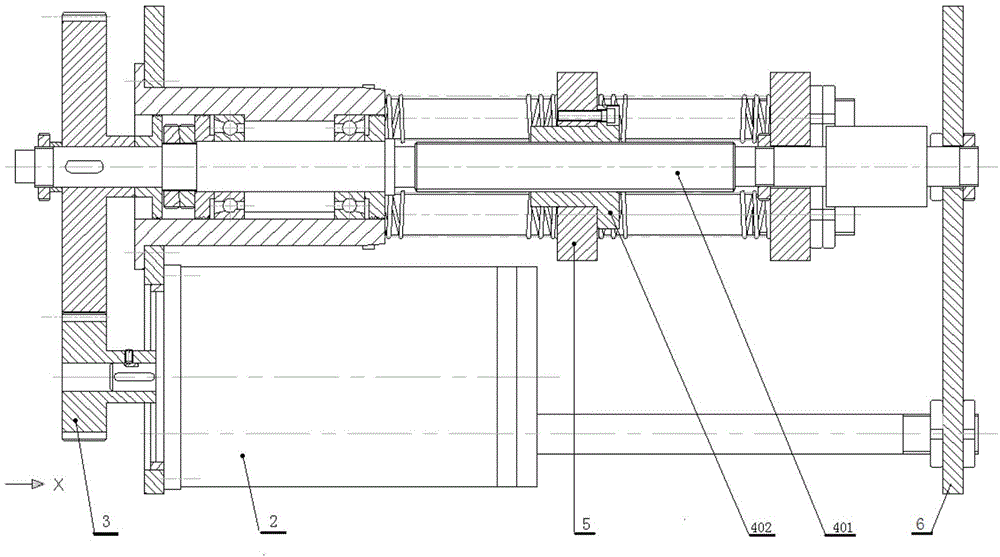
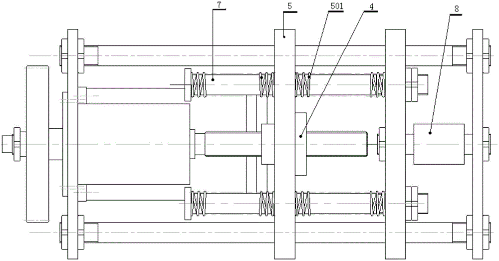
[0029] This embodiment provides a two-way tension / compression structure scheme, the digital control precision loading mechanism in this embodiment, such as Figure 1-3 As shown, it includes a controller 1, a motor 2, a transmission mechanism 3, a screw pair transmission mechanism 4 and a spring group actuator 5, and the screw pair transmission mechanism 4 in this embodiment can be a common sliding screw / nut pair, or It can be a ball screw / nut pair. The motor 2 and the screw pair transmission mechanism 4 are installed on the support plate 6 and located on the same side of the support plate 6. This structure makes the axial dimension of the precision loading mechanism compact.

[0030] The motor 2 drives the active part 401 of the helical auxiliary transmission mechanism to rotate through the transmission mechanism 3. Specifically, the transmission mechanism can be any one of gear transmission, worm gear / worm transmission, synchronous toothed belt transmission or coupling transmi...

Embodiment 2

[0045] This embodiment provides a kind of unidirectional tensile structure scheme: as Figure 4-5 As shown, the difference between it and Embodiment 1 is that a compression spring group is installed on one side (left side) of the nut. Or install a tension spring group on one side (right side) of the nut.

Embodiment 3

[0047] This embodiment provides a one-way compression structure scheme: such as Figure 6-7 As shown, the difference between it and Embodiment 1 is that a compression spring group is installed on one side (right side) of the nut. Or install a tension spring group on one side (left side) of the nut.


PUM


Abstract

The invention discloses a digital control precision loading mechanism, belongs to the fields of mechanical testing techniques and mechanical experiments, and aims at solving the problem of precise quantitative loading of experiment materials. According to the technical main points, the digital control precision loading mechanism comprises a controller, an electric motor, a transmission mechanism, a screw pair transmission mechanism and a spring group executing mechanism, wherein the electric motor is used for driving a driving part of the screw pair transmission mechanism to rotate through mechanical transmission, so that a driven part of the screw pair transmission mechanism carries out axial movement; the axial movement principle of the driven part of the screw pair transmission mechanism is determined by programming of the controller and corresponding control on the movement of the electric motor; the spring group executing mechanism is capable of compressing or stretching a spring group due to the axial movement; the compression amount or the stretching amount of the spring group is transformed into the loading amount, so as to dive the loaded object; and the loading amount, the loading speed and the accelerated speed of the loaded object are controlled according to the axial movement principle. The digital control precision loading mechanism has the beneficial effects that the digital control precision loading mechanism is high in control accuracy and can be applied to occasions with high repeat accuracy requirements.

Description

technical field [0001] The invention belongs to the field of mechanical testing technology and mechanical experiment, and is a digital control mechanism, especially a control and testing device for mechanical automatic testing such as mechanical precision testing, sensor precision calibration, material precision testing and electromechanical integration experiments. Background technique [0002] The loading mechanism is a commonly used mechanism for mechanical testing equipment. It can convert the movement of the motor or hydraulic system into the expected loading movement. The object under test is loaded accordingly. However, the general loading mechanism also has great limitations in practical applications: it cannot realize the precise quantitative loading of the test material and obtain the mechanical (mechanical) characteristics of the material; it cannot directly calibrate the precision sensor to obtain the calibration of the precision sensor characteristic curve, so ...

Claims


Application Information

Patent Timeline
IPC IPC(8): G01N3/14
Inventor 康晶郑琳
Owner DALIAN NATIONALITIES UNIVERSITY
Learn More