A display panel inspection fixture

A display panel and detection fixture technology, which is applied in the direction of measuring devices, optical instrument testing, machine/structural component testing, etc., can solve the problems of small cracks on the liquid crystal panel, damage to the liquid crystal panel, and easy wear and tear of the extension part 2. Problems such as grooves, etc. To achieve long service life, reduce wear and tear, and ensure the effect of bearing function

Active Publication Date: 2018-03-09
TCL CHINA STAR OPTOELECTRONICS TECH CO LTD
View PDF6 Cites 0 Cited by
  • Summary
  • Abstract
  • Description
  • Claims
  • Application Information

AI Technical Summary

Problems solved by technology

However, after repeated use of this fixture, the extension part 2 is easy to wear out grooves, and when pressed, it is easy to cause small cracks on the contact surface of the liquid crystal panel and damage the liquid crystal panel
[0004] However, if the material of the jig is changed to a composite material that is hard and not easy to wear, but the composite material is opaque black, so that the part of the jig that is in contact with the liquid crystal panel is black, forming a dark shadow during the lighting inspection and cannot check the place

Method used


Image

  • A display panel inspection fixture
  • A display panel inspection fixture
  • A display panel inspection fixture

Examples


Embodiment Construction

[0026] In order to make the object, technical solution and advantages of the present invention more clear, the present invention will be further described in detail below in conjunction with the accompanying drawings and embodiments. It should be understood that the specific embodiments described here are only used to explain the present invention, not to limit the present invention.

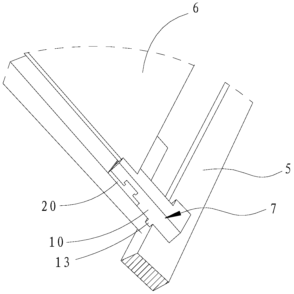
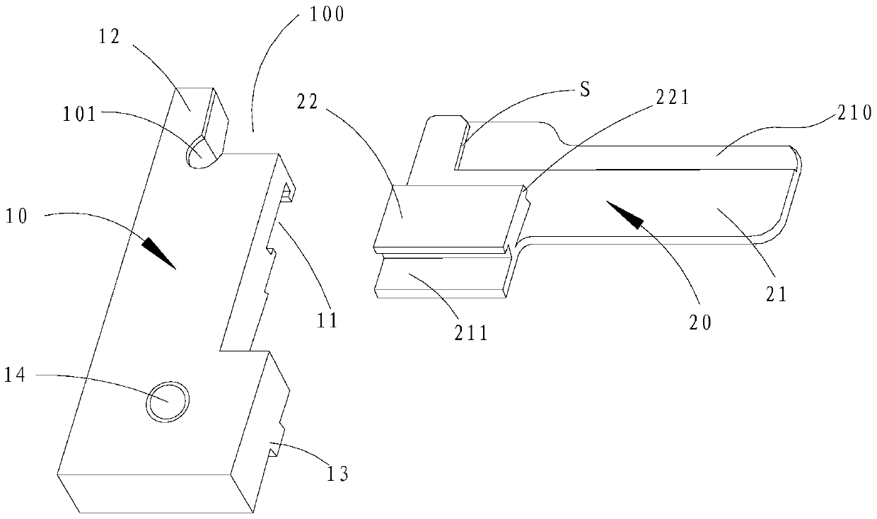
[0027] refer to figure 2 , the display panel detection jig 7 of the present invention is fixed on the detection platform 5, and is arranged at the corner of the display panel 6, and is used to make the display panel suspended and fixed on the detection platform 5 for lighting detection. The detection fixture 7 includes a briquetting block 10 and a supporting sheet 20, the briquetting block 10 is elongated and made of a composite material, and is used to extrude two adjacent side walls of the corner of the display panel 6, and the supporting sheet 20 It is detachably fixed on the detection plat...


PUM


Abstract

The invention discloses a display panel detection jig, comprising a press block and a support sheet, wherein the press block is used for being fixed on a detection platform; the support sheet is made of a transparent material, is detachably connected with the press block and partially extends out of the press block; the support sheet is used for supporting the display panel. According to the design, the display panel detection jig disclosed by the invention is composed of two plates spliced together, wherein the support sheet used for supporting the display panel is made of the transparent material, so that the light transmission requirement of a light-up test can be met and the function of supporting the display panel is ensured; the press block used for fixing is made of an anti-wear and high-hardness material, so that the wear phenomenon in use can be reduced, and therefore, the service life of the jig is prolonged.

Description

technical field [0001] The invention relates to the field of display technology, in particular to a display panel inspection jig. Background technique [0002] At present, in the manufacturing and testing departments of laboratories or factories, it is often necessary to use lighting devices to perform lighting tests on LCD panels of different types and sizes, so as to detect whether there are defects such as dead pixels or bright spots on the LCD panels after lighting. . [0003] Such as figure 1 As shown, there is a jig for auxiliary detection in the prior art, which is integrally made of transparent PC (abbreviation for polycarbonate)) material, including a fixing part 1 with a right-angle notch and a piece covering the upper surface of the notch. The principle of the lamellar extension part 2 is that after placing the liquid crystal panel on the detection platform, use the jig to place it at the corresponding corner of the liquid crystal panel, so that the correspondin...

Claims


Application Information

Patent Timeline
Patent Type & Authority Patents(China)
IPC IPC(8): G02F1/13
CPCG01M11/00G02F1/1309
Inventor 幸灵凤
Owner TCL CHINA STAR OPTOELECTRONICS TECH CO LTD
Why Eureka
Try Eureka