

Touch stylus with wireless charging function and operating method thereof
A technology of wireless charging and operation method, applied in the direction of electrical components, circuit devices, electromagnetic wave systems, etc., can solve the problem of easy interference between the charging circuit and the frequency of the AC signal, etc.
- Summary
- Abstract
- Description
- Claims
- Application Information
AI Technical Summary
Problems solved by technology
Method used
Image

Examples
Embodiment Construction
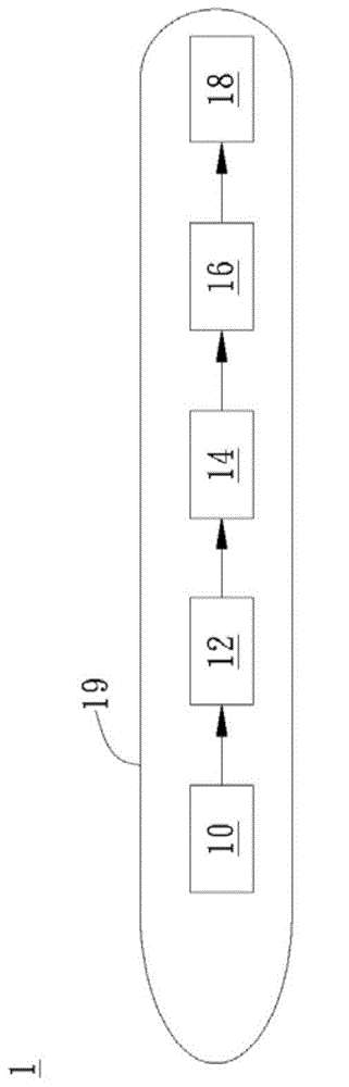
[0046] A specific embodiment according to the present invention is a touch pen with wireless charging function. In this embodiment, the stylus is used to touch the touch panel of the electronic device, but it is not limited thereto. First, please refer to figure 1 , figure 1 This is the functional block diagram of the stylus in this embodiment.
[0047] Such as figure 1 As shown, the stylus 1 with wireless charging function includes a receiving coil 10 , a resonant circuit 12 , a rectifying circuit 14 and a regulated output circuit 16 . Wherein, the resonant circuit 12 is coupled to the receiving coil 10 . The rectification circuit 14 is coupled to the resonant circuit 12 . The regulated output circuit 16 is coupled to the rectification circuit 14 . In practical applications, the stylus 1 may further include a rechargeable battery 18 . The rechargeable battery 18 can be coupled to the voltage-stabilizing output circuit 16 for storing the power output by the voltage-stab...
PUM
 Abstract
Description
Claims
Application Information