
Speaker module

A speaker module and speaker technology, applied in speaker screen, speaker transducer fixing, sensor and other directions, can solve the problems of reducing the service life of the module, difficult sealing, low product qualification rate, etc. The effect of reducing the difficulty of processing and simple assembly process

Active Publication Date: 2015-07-22
GOERTEK INC
View PDF7 Cites 16 Cited by
  • Summary
  • Abstract
  • Description
  • Claims
  • Application Information

AI Technical Summary

Problems solved by technology

At present, the speaker unit is usually positioned by a positioning structure arranged on the module shell, and then fixed on the module shell by applying glue and sealing. This kind of module that sets a positioning structure on the module shell to fix the speaker unit, its mold The structure of the group shell is very complicated, the processing of the module shell is difficult, and the positioning structure will occupy the space of the module inner cavity, which seriously affects the acoustic performance of the module; at the same time, the glue coating and sealing process is complicated, and the fixing firmness is poor. Easy to crack, which seriously reduces the service life of the module
[0003] Due to the continuous development of portable electronic devices in the direction of thinness and compactness, the structure of the speaker module must also adapt to the changes in the internal space of the electronic device. In order to ensure the acoustic performance of the module, it is necessary to ensure that the space inside the module is large enough , so that the structure of the speaker module is mostly irregular, so that the speaker unit in some modules will be infinitely close to the edge of the module shell, and even some parts of the speaker unit will be exposed outside the module shell. It is more difficult to seal the inner cavity of the speaker module with the exposed part of the monomer. At present, the commonly used solution is to apply a large amount of sealant between the speaker monomer and the module shell. This sealing method is not only difficult to assemble, but also High complexity and high production cost; at the same time, poor sealing, low appearance quality and low product qualification rate

Method used


Image

  • Speaker module
  • Speaker module
  • Speaker module

Examples


Embodiment Construction

[0032] Below in conjunction with accompanying drawing and embodiment, further elaborate the present invention.

[0033] The orientation mentioned in this manual refers to the direction of the vibration system of the speaker unit, and the direction below refers to the direction of the magnetic circuit system of the speaker unit; the inner side referred to in this manual refers to the inner cavity of the module or the inner cavity of the monomer. The inner side and the outer side both refer to the side outside the inner cavity of the module or the inner cavity of the monomer.

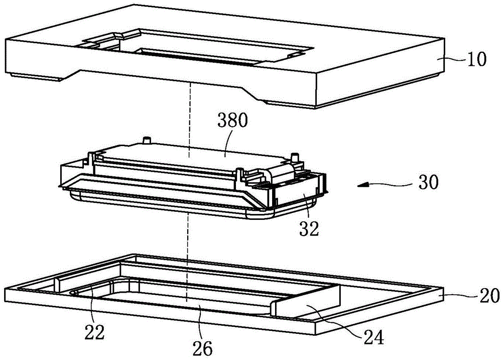
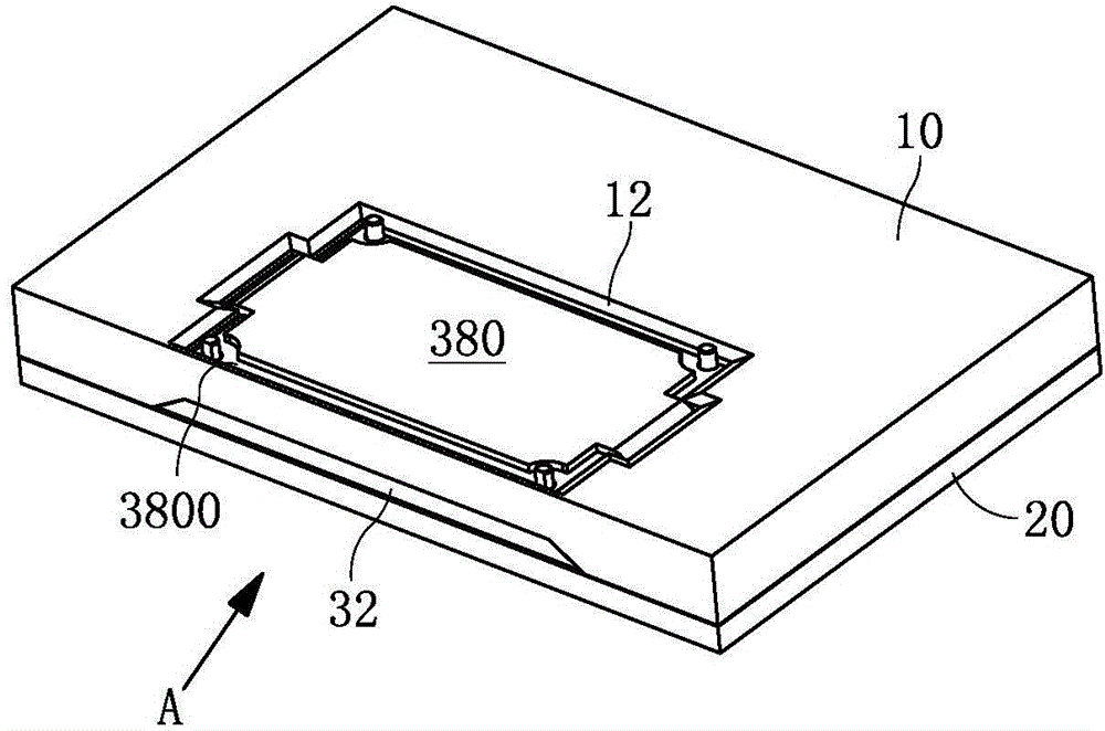
[0034] Such as figure 1 and figure 2Commonly shown, a loudspeaker module has a rectangular structure and includes a casing. The casing is composed of an upper casing 20 and a lower casing 10 combined together. A speaker unit 30 is accommodated in the space enclosed by the upper casing 20 and the lower casing 10. The loudspeaker unit 30 is also a rectangular structure, and the loudspeaker unit 30 is loc...


PUM


Abstract

The invention discloses a speaker module and relates to the technical field of electroacoustic products. The speaker module comprises a housing; a single speaker is held within the housing; the single speaker comprises a single shell and a single front cover combined together; the single shell and the single front cover form a space in which a vibrating system and a magnetic circuit system are held; the end face of at least one sidewall of the single shell is provided with an ultrasonic face to be ultrasonically welded to the housing; the housing is provided with an ultrasonic line in ultrasonic joint with the ultrasonic face and corresponding to the ultrasonic face. The technical problems such that the prior speaker module is complex to assemble, poor in tightness and poor in appearance are solved; the speaker module is simple to assemble, good in tightness, high in appearance quality, good in acoustic performance, high in production efficiency and low in production cost.

Description

technical field [0001] The invention relates to the technical field of electroacoustic products, in particular to a loudspeaker module. Background technique [0002] The loudspeaker module is an important acoustic component of portable electronic equipment, which is used to complete the conversion between electrical signals and sound signals, and is an energy conversion device. Existing loudspeaker modules usually include a module casing, in which a speaker unit is accommodated, and the speaker unit divides the entire module inner cavity into two cavities, a front acoustic cavity and a rear acoustic cavity. At present, the speaker unit is usually positioned by a positioning structure arranged on the module shell, and then fixed on the module shell by applying glue and sealing. This kind of module that sets a positioning structure on the module shell to fix the speaker unit, its mold The structure of the group shell is very complicated, the processing of the module shell is ...

Claims


Application Information

Patent Timeline
Patent Type & Authority Applications(China)
IPC IPC(8): H04R1/20H04R31/00
CPCH04R31/00H04R1/023H04R1/025H04R1/02
Inventor 李兆鹏刘华伟宋学平韩志磊
Owner GOERTEK INC
Learn More