Data transmission method, base station and terminal equipment

A data transmission method and terminal equipment technology, which is applied in the field of data transmission methods, base stations and terminal equipment, and can solve problems such as ambiguity

Active Publication Date: 2015-07-22
DATANG MOBILE COMM EQUIP CO LTD
View PDF4 Cites 34 Cited by
  • Summary
  • Abstract
  • Description
  • Claims
  • Application Information

AI Technical Summary

Problems solved by technology

However, at present, there is no clear method for how LTE systems work on unlicensed spectrum resources, and how multiple LTE systems can s

Method used


Image

  • Data transmission method, base station and terminal equipment
  • Data transmission method, base station and terminal equipment
  • Data transmission method, base station and terminal equipment

Examples


Embodiment 1

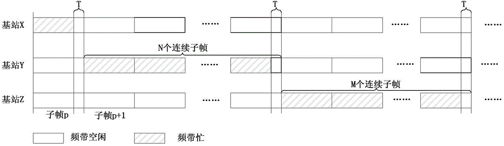
[0109] image 3 is a schematic diagram of the principle of the data transmission method in this embodiment, from image 3 It can be seen from the figure that LTE base station Y detects on the unlicensed frequency band. If it finds that the carrier is idle for at least T microseconds in a specific time period in any subframe p, it means that the carrier is currently idle. At this time, it can be in subframe p+1 Start to occupy consecutive N subframes for data transmission on the carrier.

[0110] In order to achieve fair and efficient use of unlicensed frequency band resources by multiple LTE base stations, base station Y can also idle the frequency band in the last part of the time period when it occupies unlicensed frequency band resources, so that other base stations can perform frequency band detection during this time period , once other base stations detect that the frequency band is free, they can immediately occupy the frequency band for data transmission in the next s...

Embodiment 2

[0112] Figure 4 is a schematic diagram of the principle of the data transmission method in this embodiment, from Figure 4 It can be seen from , that subframe p includes a first time period, a second time period, and a third time period. Base station Y does not schedule data transmission during the first time period of subframe p, and detects that the frequency band is idle during the second time period of subframe p, and then sends a PSS (Primary sync signal, Primary synchronization signal) / SSS (supplement sync signal, secondary synchronization signal) and measurement RS (Reference signal, reference signal), and continuously schedule N subframes for data transmission starting from subframe p+1, where N subframes can All are downlink subframes, or all are uplink subframes, or some downlink subframes, some uplink subframes, or some downlink subframes, some special subframes, or some downlink subframes, some special subframes, and some uplink subframes . Base station Y is id...

Embodiment 3

[0114] Figure 5 is a schematic diagram of the principle of the data transmission method in this embodiment, from Figure 5 It can be seen from , that subframe p includes a first time period, a second time period, and a third time period. Base station Y does not schedule data transmission in the first time period of subframe p, and detects the frequency band space in the second time period of subframe p, and then sends PSS / SSS and measurement RS in the third time period of subframe p , and starting from subframe p+1, N subframes are continuously scheduled for data transmission, wherein, all of the N subframes can be downlink subframes, or all can be uplink subframes, or part of downlink subframes, part of uplink subframes, or Some downlink subframes, some special subframes, or some downlink subframes, some special subframes, and some uplink subframes. Base station Y is idle for the second time period in subframe p+N. During this time period, all base stations and nodes (LTE,...


PUM


Abstract

Disclosed is a data transmission method. In one aspect, the method comprises: a base station detecting a preset frequency band, and determining whether an idleness of a first time period exists in a subframe p of the preset frequency band in a preset time segment; and if the detection result is yes, a base station scheduling data on N consecutive subframes starting from a following subframe of the subframe p and transmitting the data, and setting A last symbols of a last subframe among the N consecutive subframes to be idle, N and A being both positive integers. In another aspect, the method comprises: a user equipment detecting downlink control signaling (DCI), the DCI being used for scheduling a user equipment to receive or send data in a subframe p of a preset frequency band; if the DCI is detected, the user equipment determining a last idle symbol B in the subframe p according to the DCI, B being a nonnegative integer; and the user equipment receiving or sending data in the subframe p of the preset frequency band according to the number B of idle symbols B.

Description

technical field [0001] The present invention relates to the technical field of mobile communication, in particular, to a data transmission method, base station and terminal equipment. Background technique [0002] 1. LTE (Long Term Evolution, long-term evolution) system [0003] The LTE system supports FDD (Frequency Division Duplexing, frequency division duplexing) and TDD (Time Division Duplexing, time division duplexing) two duplex modes, and the two duplex modes use different frame structures. The common point of the two frame structures is that each radio frame is composed of 10 1ms subframes. Among them, the FDD system uses the first type of frame structure, and the TDD system uses the second type of frame structure. In the first type of frame structure, the transmission directions of 10 subframes in one radio frame are the same, all being uplink or downlink. In the second type of frame structure, each radio frame includes three different subframes: downlink subfram...

Claims


Application Information

Patent Timeline
IPC IPC(8): H04W24/00H04W72/04
CPCH04W24/00H04W72/52H04W16/14H04W74/0816H04W72/1273H04W72/23H04W72/0446H04W72/0453
Inventor 林亚男沈祖康高雪娟司倩倩
Owner DATANG MOBILE COMM EQUIP CO LTD
Why Eureka
Try Eureka