Electroless self-starting firefighting extinguishing system

A fire extinguishing system and self-starting technology, applied in fire rescue and other directions, can solve problems such as loss of people's lives and property safety, long time for fire signal collection, and failure of the fire protection system to ensure the safety of people's lives and property and reduce installation Steps, the effect of shortening the fire extinguishing time

Inactive Publication Date: 2015-07-29
施建明
View PDF6 Cites 2 Cited by
  • Summary
  • Abstract
  • Description
  • Claims
  • Application Information

AI Technical Summary

Problems solved by technology

[0002] Existing fire protection systems include sensors, nozzles and electrical monitoring units. The sensors include smoke sensors or temperature sensors. When the monitoring unit judges a higher smoke concentration signal or a higher temperature signal, it will determine that a fire has occurred in the monitoring area, then control the nozzle to open, spray out fire extinguishing substances, and carry out fire extinguishing. The devices required by the existing fire protection system are relatively Many, inconvenient installation, high cost, long time to collect fire signals, not convenient for timely and effective fire extinguishing, if the smoke in the monitoring area is large or the temperature is high, but there is no fire, it is very easy to misfire and waste resources , it requires a dedicated power supply or a backup power supply to supply power to the electrical monitoring unit. When the power supply or electrical monitoring unit is damaged, or the fire source is near the electrical monitoring unit or power supply, and the electrical monitoring unit or power supply is directly burned out, the fire protection system cannot work. Great loss to people's life and property safety

Method used


Image

  • Electroless self-starting firefighting extinguishing system
  • Electroless self-starting firefighting extinguishing system

Examples


Embodiment Construction

[0009] In order to make the technical means, creative features, goals and effects achieved by the present invention easy to understand, the present invention will be further described below in conjunction with specific illustrations.

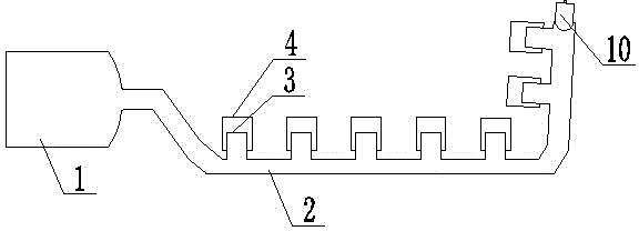
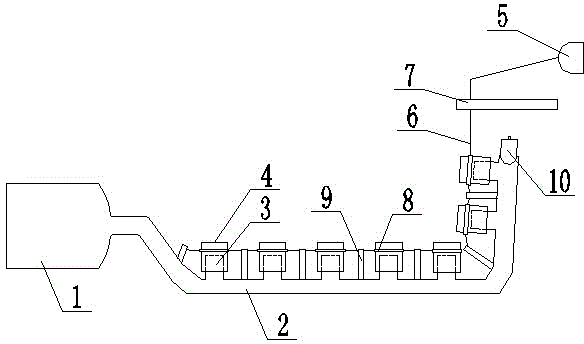
[0010] Such as figure 1 As shown, the present invention includes a fire extinguishing material storage tank 1, a conduit 2 and a nozzle 3. The nozzle 3 is fixedly connected to the conduit 2 and communicates with the conduit 2. The outlet end of the fire extinguishing material storage tank 1 communicates with the head end of the conduit 2. The nozzle 3 is sleeved with a frangible nozzle cover 4 which can seal the nozzle and is made of fusible material.

[0011] The present invention can install the nozzle in the fire-prone area. When the ambient temperature reaches the melting point of the nozzle cover, the nozzle cover will start to melt to form a natural nozzle opening, and the fire extinguishing material in the fire extinguishing material stor...


PUM


Abstract

The invention relates to an electroless self-starting firefighting extinguishing system. The powerless self-starting firefighting extinguishing system is characterized by comprising an extinguishing material storage tank, a guide pipe and a spray nozzle, wherein the spray nozzle is fixedly connected to the guide pipe and is communicated with the guide pipe, the outlet end of the extinguishing material storage tank is communicated with a head end inlet of the guide pipe, the spray nozzle is sleeved by a spray nozzle housing which can seal the spray nozzle and is made of a material easy to smelt. Compared with the prior art, the electroless self-starting firefighting extinguishing system has the following advantages that the structure is simple, easiness in installation can be realized, and the cost is low; the opening of the spray nozzle is realized to carry out the automatic extinguishing by virtue of the spontaneous smelting of the spray nozzle housing after being suffered from the high temperature, starting a power supply is not needed, the extinguishing time is shortened, timeliness in extinguishing can be realized, the fault extinguishing can be avoided, the resource waste is reduced, and the life and property safety of people can be guaranteed.

Description

technical field [0001] The invention relates to a fire-fighting system, in particular to a self-starting fire-fighting and extinguishing system. Background technique [0002] Existing fire protection systems include sensors, nozzles and electrical monitoring units. The sensors include smoke sensors or temperature sensors. When the monitoring unit judges a higher smoke concentration signal or a higher temperature signal, it will determine that a fire has occurred in the monitoring area, then control the nozzle to open, spray out fire extinguishing substances, and carry out fire extinguishing. The devices required by the existing fire protection system are relatively Many, inconvenient installation, high cost, long time to collect fire signals, not convenient for timely and effective fire extinguishing, if the smoke in the monitoring area is large or the temperature is high, but there is no fire, it is very easy to misfire and waste resources , it requires a dedicated power ...

Claims


Application Information

Patent Timeline
Patent Type & Authority Applications(China)
IPC IPC(8): A62C31/02A62C37/11
CPCA62C31/02A62C37/11
Inventor 施建明
Owner 施建明
Why Eureka
Try Eureka