
Device for straightening curved continuous casting billets

A continuous casting billet and straightening technology, applied in the field of steelmaking production, can solve the problems of low upper surface temperature, bending, waste of manpower and material resources, etc., and achieve the effects of low manufacturing cost, lowering production cost and reducing scrap rate

Inactive Publication Date: 2015-07-29
ZENITH STEEL GROUP CORP
View PDF5 Cites 1 Cited by
  • Summary
  • Abstract
  • Description
  • Claims
  • Application Information

AI Technical Summary

Problems solved by technology

When billet continuous casting billets are stacked, the stacking method of "Tac-toe" is often used. During the hoisting process, the lower surface of the red-hot billets stacked is in contact with the previous layer of billets, and the upper surface is directly in contact with the air. Contact makes the upper surface and both ends of the slab cool faster than the lower surface, resulting in a lower temperature on the upper surface of the slab. According to the principle of thermal expansion and contraction, the upper surface shrinks more than the lower surface, causing the slab to produce a bending phenomenon at both ends. , which seriously affects the quality of the continuous casting slab, and even cannot enter the walking heating furnace
[0003] Especially in the production of alloy steel, the alloy content is high. When the continuous casting slab is stacked and cooled, it is easy to bend at both ends, so that the continuous casting slab cannot enter the walking heating furnace. Due to the high cost of alloy steel, if the bending is continuously Cutting the slab and returning it to the furnace will inevitably cause serious waste of manpower and material resources, and may affect the production rhythm and the delivery date of the finished product. Therefore, effective measures must be taken to straighten the curved continuous casting slab. After straightening, the continuous casting The billet is kept straight, and enters the next process after reaching the standard

Method used


Image

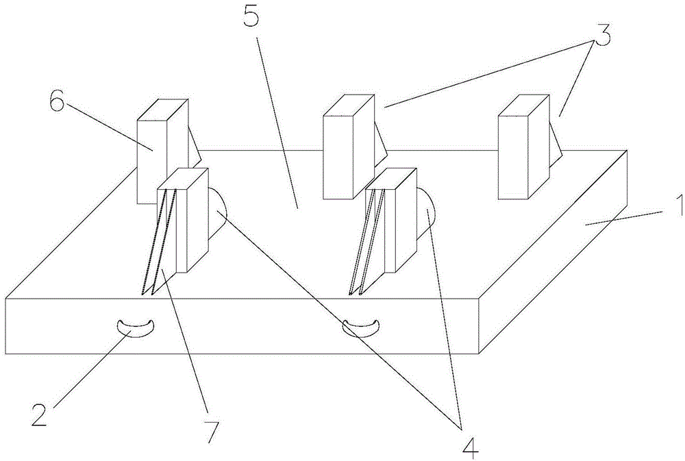
  • Device for straightening curved continuous casting billets
  • Device for straightening curved continuous casting billets
  • Device for straightening curved continuous casting billets

Examples


Embodiment 1

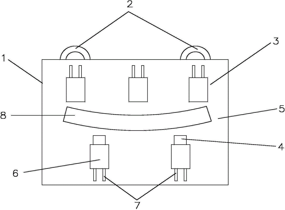
[0025] Embodiment one: if figure 2 As shown, the first row of support units includes two support units 3, and the distance between the two support units 3 is 1 / 4 to 1 / 2 of the length of the continuous casting slab 8; the second row of support units includes three support units, The three supporting units 3 are equally spaced, the distance between the supporting units 3 at both ends is greater than 1 / 2 of the length of the continuous casting slab 8 and less than or equal to the length of the continuous casting slab 8, and the two supporting units (3) in the first row Located on both sides of the support unit (3) in the middle of the second row. Embodiment 1 illustrates the minimum distribution quantity when the quantity of two rows of support units 3 distributed on the frame 1 is not equal, the quantity of two rows of support units 3 can be greater than the design quantity of the above-mentioned single row, but it must be ensured that the distribution in the length direction s...

Embodiment 2

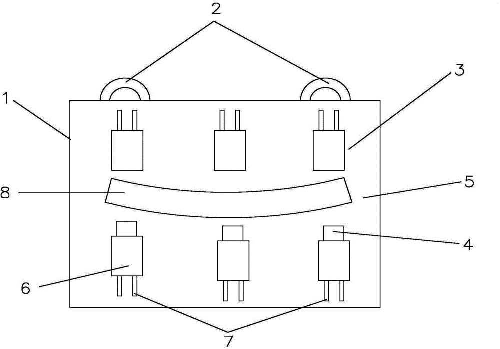
[0026] Embodiment two: if image 3 As shown, the support units 3 of the first row of support units and the second row of support units are symmetrically distributed, each row has at least three and the intervals are evenly distributed, and the distance between the support units 3 at both ends of each row is greater than 1 / 2 of the length of the continuous casting slab 8 And less than or equal to the length of the continuous casting slab 8 . Embodiment 2 illustrates the minimum distribution quantity when the number of supporting units distributed on both sides of the axis of the frame 1 is equal. This method has no requirements for the placement direction of the continuous casting slab 8, but it is also necessary to ensure that there are 3 supporting units at both ends of each row. The distance is greater than 1 / 2 of the length of the continuous casting slab 8 and less than or equal to the length of the continuous casting slab 8 . When the number of support units 3 in each row...

Embodiment 3

[0027] Embodiment three: as Figure 4 As mentioned above, when there are three support units in the first row and four support units in the second row, the distribution method in Embodiment 2 can also be adopted, the support units 3 in each row are evenly distributed, and the support units at both ends of each row are 3 The distance is greater than 1 / 2 of the length of the continuous casting slab 8 and less than or equal to the length of the continuous casting slab 8, but the two rows of support units 3 are not symmetrically distributed.

[0028] The hydraulic jack that jack 4 among the present invention adopts can also adopt mechanical jack.

[0029] When in use, place the lifting hook of the crane on the lifting lug 2, and move it to the side of the stack of curved continuous casting billets 8, hoist the curved continuous casting billets 8 to the center of the rectangular frame 1, and turn the bending direction away from the Hold the direction of the hydraulic jack 4, and t...


PUM


Abstract

The invention provides a device for straightening curved continuous casting billets. The device comprises a frame and a continuous casting billet straightening structure arranged on the frame, wherein the continuous casting billet straightening structure comprises a supporting unit and a jack arranged on the supporting unit, and the supporting unit forms a first-row supporting unit and a second-row supporting unit; the first-row supporting unit and the second-row supporting unit are arranged on the frame side by side, and a space for containing the continuous casting billets is formed between the first-row supporting unit and the second-row supporting unit. By straightening the continuous casting billets being bent and deformed due to non-uniform cooling in the stacking process, the method can effectively make the original bent deformed continuous casting billets flat and straight, and the continuous casting billets enter the next procedure smoothly. Therefore, the percent of pass of casting billets is furthest increased, the rejection rate of casting billets is reduced, and the production cost is reduced. The device has the advantages of being simple in structure, low in manufacture cost and easy to operate and is suitable for popularization and application in the industry.

Description

technical field [0001] The invention relates to the technical field of steelmaking production, in particular to a device for straightening curved continuous casting slabs. Background technique [0002] During the billet continuous casting production process, the continuous casting slab is transported to the cooling bed after being flame-cut, and after being turned over, it is pushed to move on the cooling bed by a pusher, and then hoisted to the designated finished product stomping position. When billet continuous casting billets are stacked, the stacking method of "Tac-toe" is often used. During the hoisting process, the lower surface of the red-hot billets stacked is in contact with the previous layer of billets, and the upper surface is directly in contact with the air. Contact makes the cooling rate of the upper surface and both ends of the slab faster than that of the lower surface, resulting in a lower temperature on the upper surface of the slab. According to the prin...

Claims


Application Information

Patent Timeline
Patent Type & Authority Applications(China)
IPC IPC(8): B21D3/10
CPCB21D3/10
Inventor 豆乃远
Owner ZENITH STEEL GROUP CORP
Learn More