
Differential type bearing removing device

A bearing dismounting device and differential technology, which is applied to hand-held tools, manufacturing tools, etc., can solve the problems of large moving stroke of the central threaded shaft, large size of the bearing dismounting tool, and bulky body, etc. Simple, shortened stroke length effect

Inactive Publication Date: 2015-07-29
CHINA UNIV OF PETROLEUM (EAST CHINA)
View PDF6 Cites 7 Cited by
  • Summary
  • Abstract
  • Description
  • Claims
  • Application Information

AI Technical Summary

Problems solved by technology

At present, there are few special dismounting tools for bearings on the market. The working principle is mostly to clamp the lower end surface of the bearing with claws, and then turn the central threaded shaft to make the shaft on which the bearing is installed move down, so that the bearing is disassembled. During the disassembly process The larger travel of the central threaded shaft makes the bearing removal tool larger and bulkier for portability

Method used


Image

  • Differential type bearing removing device
  • Differential type bearing removing device
  • Differential type bearing removing device

Examples


Embodiment Construction

[0021] Below in conjunction with accompanying drawing and example the present invention will be further described:

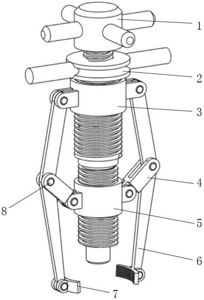
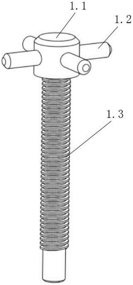
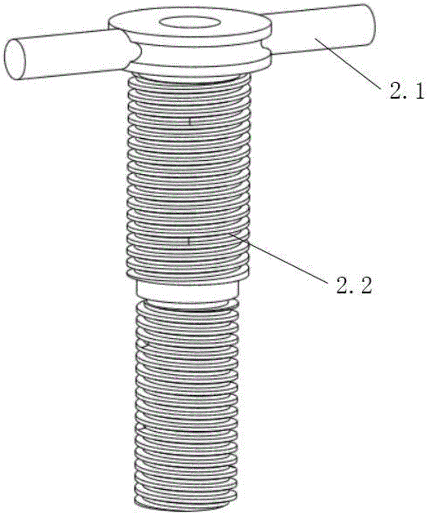
[0022] Such as Figure 1-7 As shown, a differential bearing removal device of the present invention includes a power shaft (1), a preload sleeve (2), an upper differential sleeve (3), a movable joint (4), a lower differential sleeve (5), Connecting plate (6), curved splint (7), pin (8), the power shaft (1) is screwed to the pre-tightening sleeve (2), the upper differential sleeve (3), the lower differential The sleeves (5) are threadedly connected with the pre-tightening sleeves (2), the upper end of the connecting plate (6) is connected with the upper differential sleeve (3) through pins (8), and the middle and the movable joint (4) are connected through pins (8) ), the lower end is connected with the arc splint (7) through a pin (8), one end of the movable section (4) is connected with the lower differential sleeve (5) through a pin (8), and the other end is ...


PUM


Abstract

The invention relates to bearing removing devices, in particular to a differential type bearing removing device. The differential type bearing removing device comprises a power shaft, a pre-tightening sleeve, an upper differential sleeve, movable links, a lower differential sleeve, connecting plates, arc-shaped clamping plates and pins, wherein the power shaft is in threaded connection with the pre-tightening sleeve, the upper and lower differential sleeves are in threaded connection with the pre-tightening sleeve respectively, the upper ends of the connecting plates are connected with the upper differential sleeve through bolts, the middles of the connecting plates are connected with the movable links through bolts, and the lower ends of the connecting plates are connected with the arc-shaped clamping plates through bolts. The differential type bearing removing device has the beneficial effects that the structure is simple, the use is convenient, and the upper differential sleeve and the lower differential sleeve form differential motion, so that the stroke length of the upper and lower differential sleeves on the pre-tightening sleeve is shortened, and the size of a bearing removing tool is reduced; threads are formed in inner arc faces of the arc-shaped clamping plates, so that the friction between the inner arc faces and a cylindrical face of a bearing is increased, and removal is facilitated; the disadvantages of the ordinary bearing removing tools that the size is relatively large, the structure is complicated and carrying is inconvenient are overcome, and the differential type bearing removing device has a certain practical value.

Description

technical field [0001] The invention relates to a bearing dismounting device, in particular to a differential bearing dismounting device. Background technique [0002] With the rapid development of the bearing industry, bearings are now widely used in various industries. In general machinery, deep groove ball bearings are the most common application. Deep groove ball bearings are installed on the journal near the shaft end when they are in use. The interference fit of the journal increases the difficulty of dismounting the bearing due to its large interference. At present, there are few special dismounting tools for bearings on the market. The working principle is mostly to clamp the lower end surface of the bearing with claws, and then turn the central threaded shaft to make the shaft on which the bearing is installed move down, so as to disassemble the bearing. During the disassembly process The movement stroke of the central threaded shaft is relatively large, making the...

Claims


Application Information

Patent Timeline
Patent Type & Authority Applications(China)
IPC IPC(8): B25B27/02
CPCB25B27/023B25B27/062
Inventor 孟凡林张琦李乐乐刘晓聪康强荆正军陈志达侯华敬
Owner CHINA UNIV OF PETROLEUM (EAST CHINA)
Learn More