
Light distribution lens and system for uniform light direct-down LED backlighting and a TV

A backlighting and direct-lighting technology, which is applied in the field of backlighting to achieve the effects of increasing intensity, improving uniformity of light and reducing accumulation

Active Publication Date: 2019-02-19
CHENGDU HERCULUX OPTOELECTRONICS TECH CO LTD
View PDF7 Cites 2 Cited by
  • Summary
  • Abstract
  • Description
  • Claims
  • Application Information

AI Technical Summary

Problems solved by technology

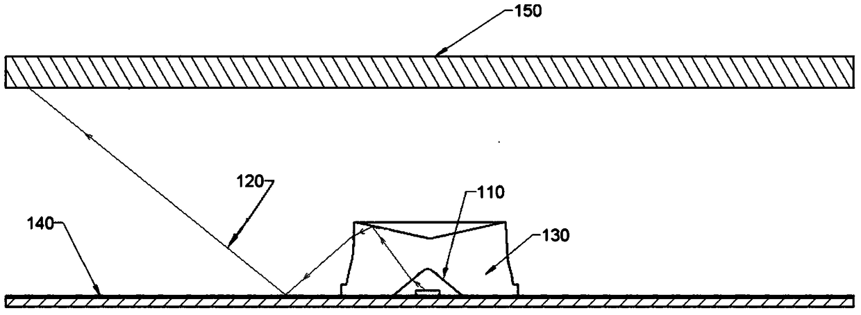
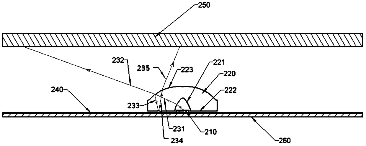
[0013] In order to overcome the problem of small-angle light accumulation near the center of the backlight lens in the prior art, the present invention provides a light distribution lens for uniform light direct-lit LED backlighting, which can reduce the incident light caused by Fresnel interface reflection in the central light. The stacking of fields and the reasonable distribution of outgoing light can reduce the number of LED light sources used on the LED backlight panel while achieving the same lighting effect. At the same time, it can also reduce the thickness from the LED light source to the diffusion plate and reduce the volume of the system.

Method used


Image

  • Light distribution lens and system for uniform light direct-down LED backlighting and a TV
  • Light distribution lens and system for uniform light direct-down LED backlighting and a TV
  • Light distribution lens and system for uniform light direct-down LED backlighting and a TV

Examples


Embodiment 1

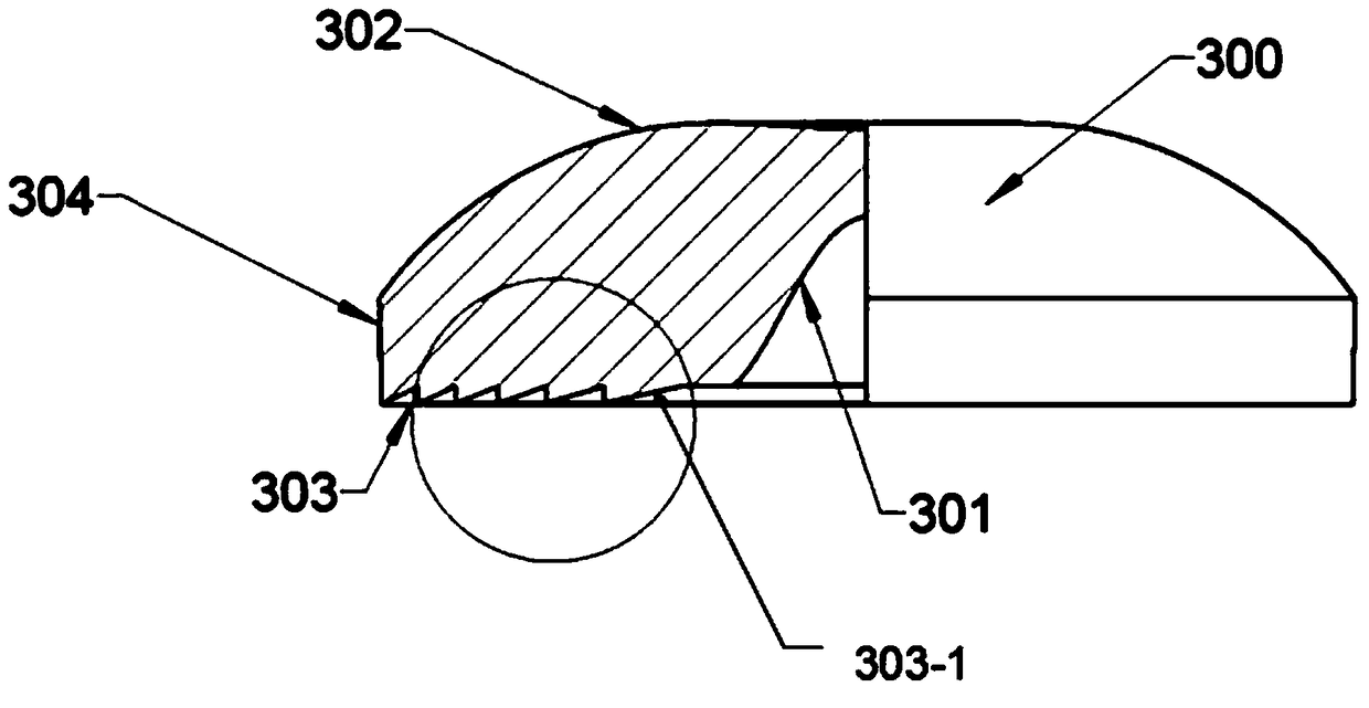
[0148] The bottom composite surface of the backlight lens in this embodiment includes a sub-composite surface, and the normal line of any point on the section of the sub-composite surface intersects with the central axis of the lens body below the lens body. In this embodiment, The lens structure in is simple and easy to mass-produce; such as Figure 6 , Figure 7 and Figure 8 shown (where Figure 6 is a schematic diagram of the three-dimensional structure of the present embodiment; Figure 7 is a schematic sectional view of the present embodiment; Figure 8 is the bottom view of the present embodiment). The rest of the structure and working principles of this embodiment are the same as those of the above-mentioned specific implementation, and will not be repeated here.

Embodiment 2

[0150] The bottom composite surface included in the backlight lens in this embodiment includes 6 sub-composite surfaces, the section line of the bottom composite surface is zigzag, and the zigzag root of the section line of the bottom composite surface is located on the same straight line, which is the same as this line. The central axis of the lens body described in the embodiment is vertical; and the section line of the sub-composite surface is a straight line structure, not only that, the arrangement of the sub-composite surfaces is denser as it gets closer to the edge of the lens body, such as Figure 9 , Figure 10 , Figure 11 shown (where Figure 9 is a schematic diagram of the three-dimensional structure of the present embodiment; Figure 10 is a schematic sectional view of the present embodiment; Figure 11 is the bottom view of this embodiment), and the rest of the structure and working principle of this embodiment are the same as those of the above-mentioned spec...

Embodiment 3

[0152] The bottom composite surface included in the backlight lens in this embodiment includes 6 sub-composite surfaces, the section line of the bottom composite surface is zigzag, and the zigzag root of the section line of the bottom composite surface is located on a curve, any point on the curve The closer to the central axis of the lens body, the greater the distance from the bottom surface of the lens; and the section line of the sub-composite surface is a straight line structure, and not only that, the arrangement of the sub-composite surfaces is denser the closer to the edge of the lens body, such as Figure 12 and Figure 13 shown (where Figure 12 is a schematic perspective view of this embodiment, Figure 13 is a schematic cross-sectional view of this embodiment), and the rest of the structure and working principle of this embodiment are the same as those of the above-mentioned specific implementation, and will not be repeated here.


PUM


Abstract

The invention relates to the technical field of backlight, in particular to a novel uniform light direct type LED (light-emitting diode) back lighting light distribution lens which comprises a lens body. The lens body comprises an incident surface, an emergent surface and a bottom composite surface, the normal of an arbitrary point on a section line of a composite subsurface in a section and the central axis of the lens body are intersected below the lens body when the composite subsurface is split along the central axis of the lens body, fresnel interface reflection light reflected by the emergent surface is reflected in a direction far away from the central axis of the lens body, accumulation of the light in a central area above the lens is effectively reduced, and light uniformity of an emergent light field is enhanced. In the same light-emitting area and on the premise of the same illumination uniformity on a diffusion plate, the distance between LED light sources can be increased, the number of LEDs is decreased, the distance between each LED light source and the diffusion plate is shortened, so that the cost and the size of a direct type LED back lighting system are reduced.

Description

technical field [0001] The invention relates to the technical field of backlighting, in particular to a light distribution lens, a system and a TV for uniform light direct type LED backlighting. Background technique [0002] There are usually two types of backlighting methods and lighting structures for LED backlighting and LED panel lights for LCD TVs: one is to place multiple LEDs on the side of the light guide plate (the optical axis of the LED is basically perpendicular to the side of the light guide plate), The light emitted by the LED enters the light guide plate through the side of the light guide plate. After multiple total reflections and refractions in the light guide plate, finally all the light is transmitted through the front of the light guide plate. By precisely controlling the ratio of reflection and refraction of the light guide plate, A uniform light-emitting surface can be formed on the front of the light guide plate; this method is often called a side-typ...

Claims


Application Information

Patent Timeline
Patent Type & Authority Patents(China)
IPC IPC(8): F21V5/04F21Y115/10
CPCF21V5/04
Inventor 霍永峰周礼书
Owner CHENGDU HERCULUX OPTOELECTRONICS TECH CO LTD
Learn More