
Orthokeratology

A technology of orthokeratology and arc segments, which is applied in glasses/goggles, optics, instruments, etc., can solve problems such as uneven joints, multiple chamfers, and unstable dioptric power differences, so as to ensure safety and effectiveness The effect of improving the surface finish and reducing the number of connecting segments

Active Publication Date: 2017-05-31
EYEBRIGHT MEDICAL TECH BEIJING
View PDF10 Cites 0 Cited by
  • Summary
  • Abstract
  • Description
  • Claims
  • Application Information

AI Technical Summary

Problems solved by technology

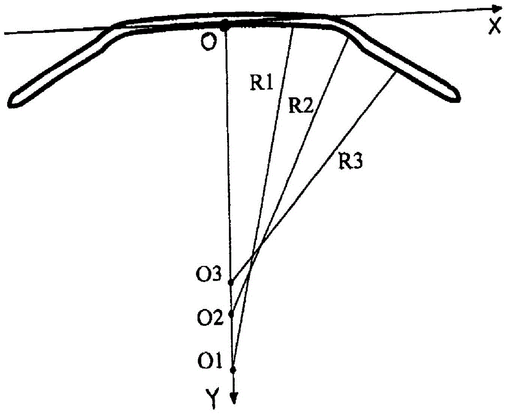
[0009] (1) The reverse arc design of the prior art orthokeratology lens adopts a circular arc on the same centerline as the base arc and the center of the positioning arc, so that the two are naturally and smoothly connected. The disadvantage of this design is that the reverse arc and the positioning arc are The refractive power difference between the base arcs is unstable, and the refractive power of the reverse arc area of ​​the existing plastic mirrors reported publicly is 3-15D larger than that of the base arc area. In fact, the difference may be far greater than the span of 3-15D, resulting in tear storage. The space capacity is unstable, and the shaping effect of plastic mirrors with different degrees of reduction is also unstable, reducing the therapeutic effect
[0010] (2) Orthokeratology lenses in the prior art focus most of their energy on the design of the inner surface, and strive to make the orthokeratology lens more comfortable to wear and achieve better shaping effects in the design direction, but do not Consider improvements in the optical performance of orthokeratology lenses
The existing positioning arc area uses several arcs with different radii of curvature to simulate the peripheral shape of the cornea. The junctions of the arcs are not smooth and require multiple chamfers, which cannot completely match the peripheral shape of the cornea.

Method used


Image

  • Orthokeratology
  • Orthokeratology
  • Orthokeratology

Examples


Embodiment Construction

[0068] The following specific examples are only used to further explain the present invention, but the present invention is not limited to the following specific embodiments. Any changes based on these embodiments, as long as they conform to the spirit and scope of the principles of the present invention, will fall within the coverage of the patent of the present invention.

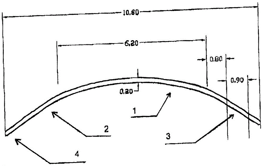
[0069] The lens thickness of the orthokeratology lens of the present invention is roughly in the range of 0.18-0.25 mm. The base arc area is the optical area of ​​the orthokeratology lens. Its diameter is designed according to the wearer's pupil size range of 5.5-7.0 mm (for example, 6.0 mm), and the radius of curvature is 7.50-9.93 mm. It adopts zero-aberration spherical design or zero-aberration aberration Spherical design.

[0070] image 3 is a schematic longitudinal central sectional view of an orthokeratology lens according to an embodiment of the present invention. Figure 4 It is another longit...


PUM


Abstract

The invention relates to an orthokeratology lens. The internal surface of the orthokeratology lens is continuously provided with a basic curve zone, a reverse curve zone, a positioning curve zone and a circumference curve zone from center to outside. The center of a circle of the basic spherical curve of the reverse curve zone is not in a line connecting the center of a circle of the basic spherical curve of the basic curve segment and the center of a circle of the basic spherical curve of the positioning curve segment. The orthokeratology lens can control a refractive power difference between the reverse curve and the basic curve in a stable value, so the stable volume of a tear storage space is guaranteed, and the wearing safety and validity of the lens is guaranteed; the matching degree of a lens matching curve zone and the shape of cornea is improved, the quantity of curve zone connecting segments is reduced, and the surface cleanness is improved; and the wearing visual sense quality of a patient is improved.

Description

technical field [0001] The present invention mainly relates to the design field of ophthalmic optics. Specifically, the present invention relates to an orthokeratology lens with a completely new design. Background technique [0002] Orthokeratology (Ortho-K) is a procedure that actively, step by step, gradually and scientifically changes the overall shape of the cornea through specially designed orthokeratology lenses, aiming at rapidly improving uncorrected vision and controlling the development of myopia in young people. technology. [0003] Modern orthokeratology lenses adopt the design principle of "inversion geometry", and the inner surface shape of the orthokeratology lens is designed to be opposite to the geometric shape of the front surface of the cornea, and some gaps are created between the lens and the cornea, and the mechanical action of tears is used to achieve " orthopedic effect. Orthokeratology lenses are rigid glasses. After wearing, there is a layer of u...

Claims


Application Information

Patent Timeline
Patent Type & Authority Patents(China)
IPC IPC(8): G02C7/04
CPCG02C7/047
Inventor 王曌解江冰甄彦杰
Owner EYEBRIGHT MEDICAL TECH BEIJING
Learn More