Multi-rotor aircraft control system, terminal and airborne flight control system

A technology for a multi-rotor aircraft and a flight control system is applied in the fields of terminals, airborne flight control systems, and multi-rotor aircraft control systems, which can solve the problem of high shooting costs, improve shooting efficiency, avoid manual control of aircraft, and save shooting costs. Effect

Inactive Publication Date: 2015-07-29
GUANGZHOU EHANG INTELLIGENT TECH
View PDF6 Cites 49 Cited by
  • Summary
  • Abstract
  • Description
  • Claims
  • Application Information

AI Technical Summary

Problems solved by technology

This requires two operators to have rich experience, and it also requires the operators to pay attention to the movement of the subject in real time, resulting in higher shooting costs

Method used


Image

  • Multi-rotor aircraft control system, terminal and airborne flight control system
  • Multi-rotor aircraft control system, terminal and airborne flight control system
  • Multi-rotor aircraft control system, terminal and airborne flight control system

Examples


Embodiment 1

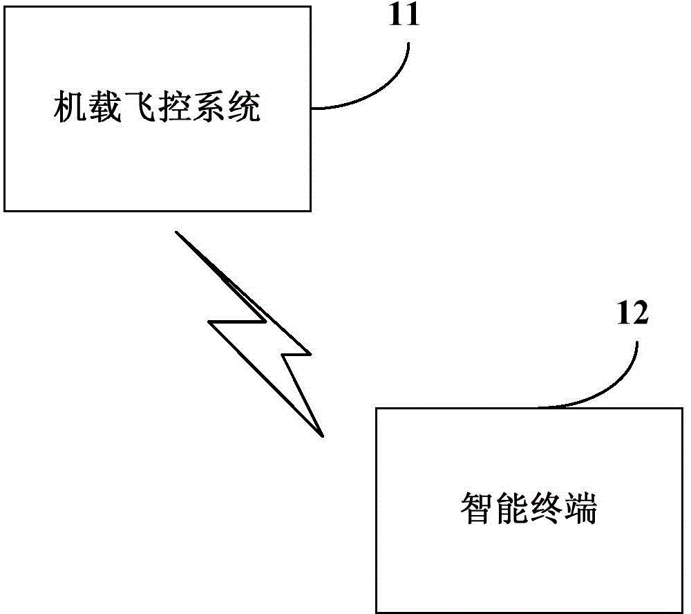
[0031] refer to figure 1 , a block diagram of a control system for a multi-rotor aircraft provided in Embodiment 1 of the present invention includes: an airborne flight control system 11 and an intelligent terminal 12 .

[0032] Wherein, the airborne flight control system 11 is used to acquire first position information, and send the first position information to the smart terminal 12, wherein the first position information is the first position information of the airborne flight control system 11 The location information of the aircraft.

[0033] The smart terminal 12 is used to obtain the second position information, and according to the second position information and the first position information sent by the airborne flight control system 11, obtain the yaw angle and the horizontal flight speed and At least one speed in the vertical flight speed, sending the yaw angle and at least one speed in the horizontal flight speed and the vertical flight speed to the airborne flig...

Embodiment 2

[0076] This embodiment provides an intelligent terminal for controlling a multi-rotor aircraft. The smart terminal can be applied to any control system of the multi-rotor aircraft provided in the above embodiments. The airborne flight control system involved in this embodiment may be the airborne flight control system provided in any control system of the multi-rotor aircraft provided in the above embodiments.

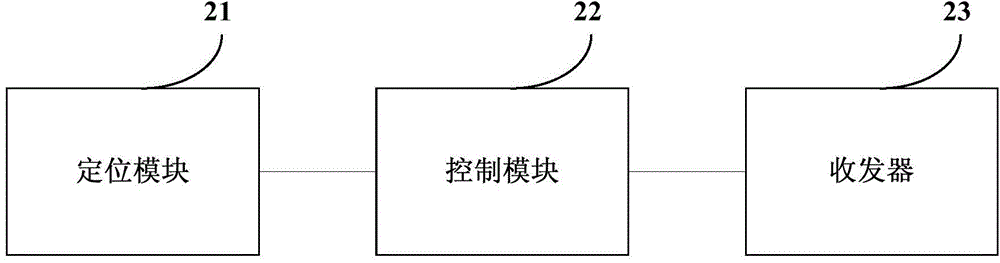
[0077] see Figure 2a , an intelligent terminal for controlling a multi-rotor aircraft provided in this embodiment includes: a positioning module 21 , a control module 22 and a transceiver 23 .

[0078] The transceiver 23 is used to receive the first location information sent by the airborne flight control system of the controlled aircraft, wherein the first location information is the location information of the aircraft where the airborne flight control system is located.

[0079] The positioning module 21 is configured to acquire the second location information, w...

Embodiment 3

[0133]This embodiment provides an airborne flight control system. The airborne flight control system can be applied to any control system of the multi-rotor aircraft provided in the above embodiments. The smart terminal involved in this embodiment may be any smart terminal provided in the foregoing embodiments.

[0134] see image 3 , an airborne flight control system provided in this embodiment includes: a positioning module 31 , a processor 32 and a transceiver 33 .

[0135] The positioning module 31 is used to obtain first location information, wherein the first location information is the location information of the aircraft where the airborne flight control system is located.

[0136] The transceiver 33 is used to send the first position information to the smart terminal, so that the smart terminal can obtain the yaw angle and the horizontal flight speed and At least one speed in the vertical flight speed, wherein the second location information is the location informa...


PUM


Abstract

The invention discloses a multi-rotor aircraft control system, a terminal and an airborne flight control system. The control system comprises an airborne flight control system and an intelligent terminal, wherein the airborne flight control system is used for acquiring first position information and sending the first position information to the intelligent terminal; the intelligent terminal is used for acquiring second position information, acquiring a yawing angle and at least one speed selected from a horizontal flight speed and a vertical flight speed according to the second position information and the first position information sent by the airborne flight control system, and sending the yawing angle and at least one speed selected from the horizontal flight speed and the vertical flight speed to the airborne flight control system; the first position information is the position information of the aircraft where the airborne flight control system is located; the second position information is the position information of the intelligent terminal; the airborne flight control system is also used for controlling the aircraft where the airborne flight control system is located to fly to the intelligent terminal according to the yawing angle and at least one speed selected from the horizontal flight speed and the vertical flight speed.

Description

technical field [0001] The invention relates to the technical field of aircraft control, in particular to a control system, a terminal and an airborne flight control system of a multi-rotor aircraft. Background technique [0002] With the development of automatic control technology, micro-sensor technology and MEMS, multi-rotor drones are gradually replacing traditional manned or unmanned helicopters and fixed-wing aircraft due to their stable performance and low cost. Used in many industries. [0003] By carrying cameras or professional imaging equipment and sensors, multi-rotor drones can easily complete various shooting tasks. For example, in the civilian field, multi-rotor drones can be used for entertainment, film and television aerial photography, power line inspection, police patrol, etc.; in the military field, they can be used for monitoring, investigation, etc. [0004] At present, when a multi-rotor UAV performs a shooting task, in order to keep the object being...

Claims


Application Information

Patent Timeline
Patent Type & Authority Applications(China)
IPC IPC(8): G05D1/08G05D1/10
CPCB64C39/024G05D1/102B64U2201/00B64U30/20B64U2201/20B64U2101/30
Inventor 胡华智
Owner GUANGZHOU EHANG INTELLIGENT TECH
Why Eureka
Try Eureka