Binding packer

A technology of packaging and machine head, which is applied to the parts of binding machinery and binding materials, etc., which can solve the problems of difficult handling, high cost and high failure rate

Inactive Publication Date: 2016-11-23
范红兵
View PDF0 Cites 1 Cited by
  • Summary
  • Abstract
  • Description
  • Claims
  • Application Information

AI Technical Summary

Problems solved by technology

However, it is difficult to realize automatic or semi-automatic packaging on the production line for materials with large volume and weight and inconvenient handling. Usually, a hand-held packaging tool is used, and the packaging belt is manually guided to wrap the material, and then the packaging belt is threaded into the machine head. The head is tightened, welded and cut off, and finally the whole process is completed
Manual packaging is inefficient and labor-intensive, while the existing large-scale packaging machines are bulky in size, expensive in cost, high in failure rate, poor in flexibility, and difficult to popularize

Method used


Image

  • Binding packer
  • Binding packer
  • Binding packer

Examples


Embodiment 1

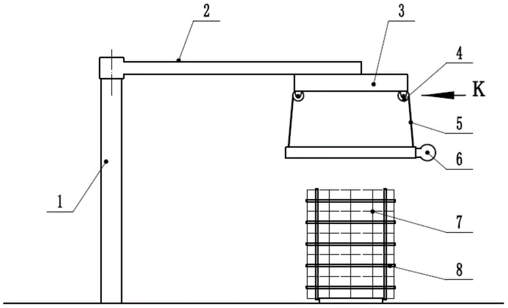
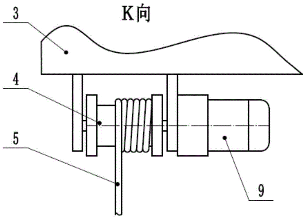
[0023] Such as figure 1 , figure 2 As shown, the site for packing materials in this example is provided with a pedestal (1) fixed on the ground, a cantilever (2) that can swing horizontally is hinged on the top of the pedestal, and a set of take-up wheels ( 4) on the top seat (3), the sling (5) is wound on the take-up wheel (4) with a power motor (9), the baler head unit (6) is connected to one end of the sling (5), and the power The motor (9) drives the take-up wheel (4) to retract and unwind the sling (5) and then pulls the baler head unit (6) to lift vertically. When performing packing work, the packing worker pulls the packing machine head unit (6) or the cantilever (2) to move horizontally, so that the packing machine head unit (6) moves to the top of the material stack (7) to be packed, and manually controls or pulls the crane The cable (5) lowers the baler head unit (6) to the position where the material is to be bundled, and the baler head unit (6) guides the packin...

Embodiment 2

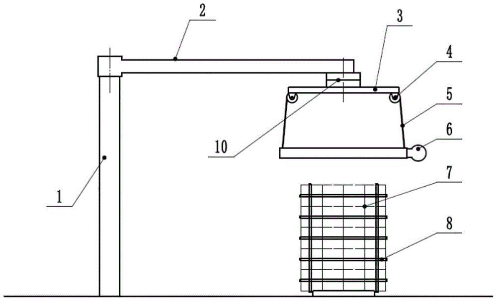
[0026] Such as figure 2 As shown, the other structure of this embodiment is the same as that of Embodiment 1, the difference is that: the top seat (3) and the cantilever (2) are connected by a rotating seat (10), so that the packer head unit (6) and The top seat (3) can rotate horizontally arbitrarily, which is more conducive to aligning the packing head unit (6) with the material. The swivel seat (10) can also have its own power, which is more conducive to the realization of automatic control.

Embodiment 3

[0028] Such as image 3 As shown, the other structure of this embodiment is the same as that of Embodiment 1, the difference is that the cantilever (2) has a slideway (11), and the top seat (3) has a pulley (12) that can slide on the slideway ). In this way, the baler head unit (6) is suspended under the cantilever (2) through the sling (5) and the top seat (3) slidingly, not only can it swing and move along the center of the hinge of the cantilever (2), but also can move along the cantilever ( 2) Radial movement to expand the working range of the baler.


PUM


Abstract

The invention provides a binding packer. The binding packer comprises a packer head unit, a top base positioned on the upper side of the packer head unit and capable of moving, and a set of lifting ropes for connecting the top base with the packer head unit; and the packer head unit is hung below the top base through the lifting ropes. The packer head unit can be horizontally operated above materials under manual traction or power driving, and is descended to a binding position of the materials through release of the lifting ropes; and finally, the packer head unit finishes automatic packing without carrying or flowing the materials, so that the labor intensity is reduced, and the working efficiency is improved.

Description

technical field [0001] The invention relates to a material packaging equipment, which belongs to the packaging industry, in particular to a binding type packaging equipment. Background technique [0002] In the packaging industry, packing tapes are often used to bundle materials. Generally, when packing small materials with packing tapes, it can be done automatically on the production line, or the materials can be transported to a baler for operation. However, it is difficult to realize automatic or semi-automatic packaging on the production line for materials with large volume and weight and inconvenient handling. Usually, a hand-held packaging tool is used, and the packaging belt is manually guided to wrap the material, and then the packaging belt is threaded into the machine head. The head is pulled tight, welded and cut, and finally the whole process is completed. Manual packing is inefficient and labor-intensive, while the existing large-scale packing machines are bulk...

Claims


Application Information

Patent Timeline
Patent Type & Authority Applications(China)
IPC IPC(8): B65B13/02B65B13/18
CPCB65B13/02B65B13/18
Inventor 范红兵
Owner 范红兵
Why Eureka
Try Eureka