Electromagnetic relay

A technology of electromagnetic relays and relays, applied in the direction of electromagnetic relays, relays, detailed information of electromagnetic relays, etc., can solve problems such as large working hours, increased component size, and shortage

Active Publication Date: 2015-07-29
LSIS CO LTD
View PDF6 Cites 24 Cited by
  • Summary
  • Abstract
  • Description
  • Claims
  • Application Information

AI Technical Summary

Problems solved by technology

[0019] However, in such a conventional electromagnetic relay, since the buffer rubber 97 is coupled in the protrusion 95 and the compression spring 25 is arranged on the upper portion of the buffer rubber 97, a gap may be formed at the buffer rubber 97, thus the elastic support of the compression spri...

Method used


Image

  • Electromagnetic relay
  • Electromagnetic relay
  • Electromagnetic relay

Examples


Embodiment Construction

[0054] Hereinafter, preferred embodiments of the electromagnetic relay according to the present invention will be described in detail with reference to the accompanying drawings.

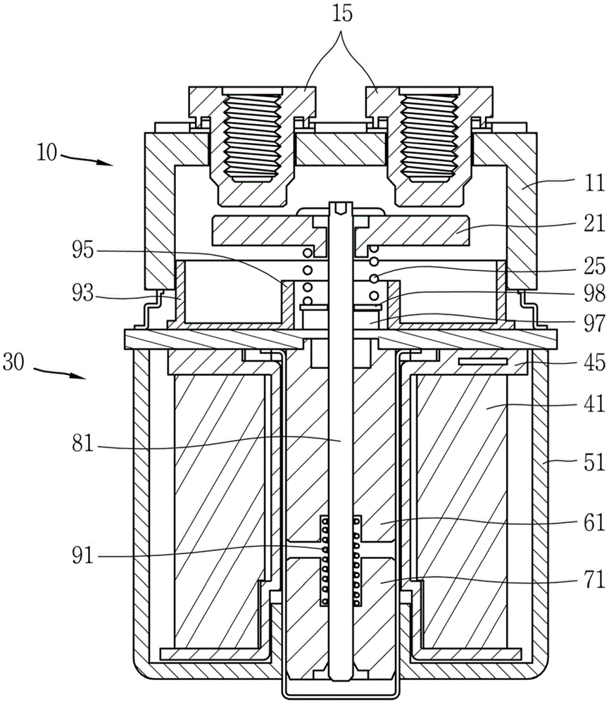
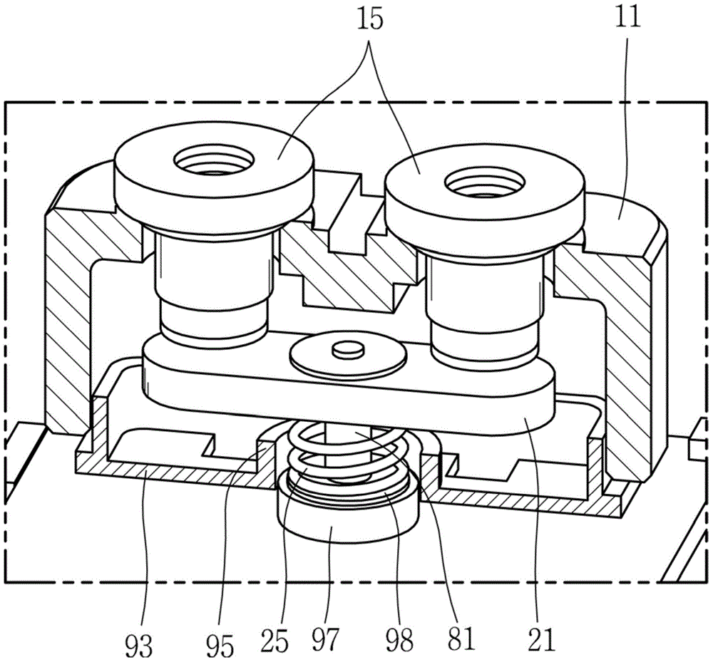
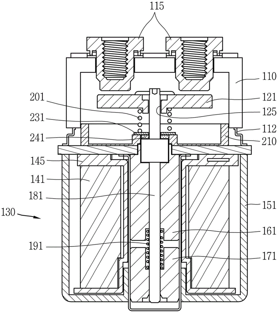
[0055] Such as image 3 and Figure 4 As shown, the electromagnetic relay according to the embodiment of the present invention may include: a casing 110; a fixed contact 115 disposed in the casing 110; a movable contact arranged in the casing 110 so as to be in contact with and separated from the fixed contact 115 Point 121; drive unit 130, which is configured to drive the movable contact 121, and includes a compression spring 201, and a shaft connected to the movable contact 121 at one end, the compression spring 201 is used to apply an elastic force to the movable contact 121 and an arc protector 210 including an arc shield portion 211 for shielding an arc and a compression spring support portion 221 formed to protrude from the arc shield portion 211 to support the compression spring 201 .

[0...


PUM


Abstract

An electromagnetic relay includes a housing; a fixed contact provided within the housing; a movable contact disposed within the housing so as to be contactable to and separable from the fixed contact; a driving unit configured to drive the movable contact, and including a shaft having one end connected to the movable contact and a compression spring for applying an elastic force to the movable contact so as to be in contact with the fixed contact; and an arc protector including an arc shielding portion for shielding an arc, and a compression spring support portion formed to protrude from the arc shielding portion to support the compression spring, the compression spring support portion comprising a shaft accommodating portion for accommodating the shaft therein. Under such configuration, the number of required components can be reduced and generation of a gap can be prevented.

Description

technical field [0001] The present invention relates to an electromagnetic relay, and more particularly, to an electromagnetic relay capable of reducing the number of man-hours in the assembly process. Background technique [0002] As known in the prior art, an electromagnetic relay is a device for opening and closing a main power supply side circuit and a load side circuit. [0003] figure 1 is a sectional view showing an electromagnetic relay according to the prior art, and figure 2 is showing figure 1 An exploded view of the main parts. [0004] Such as figure 1 and figure 2 As shown, a conventional electromagnetic relay includes a contact portion 10 and a drive portion 30 configured to open and close the contact portion 10 . [0005] The contact portion 10 includes a housing 11 , a fixed contact 15 fixedly arranged at the housing 11 , and a movable contact 21 configured to be in contact with or separated from the fixed contact 15 . [0006] The drive section 30 ...

Claims


Application Information

Patent Timeline
IPC IPC(8): H01H50/04H01H50/54H01H50/64
CPCH01H50/34H01H9/30H01H50/04H01H50/54H01H50/645H01H50/38H01H50/56H01H50/10H01H50/305
Inventor 李敬准
Owner LSIS CO LTD
Why Eureka
Try Eureka